Blogs

Our Initiatives to Utilize the Terahertz Band in Mobile Communications

#FSOC/Terahertz

Scroll

From the 1st to 4th generations (hereafter referred to as 4G), the connectivity systems for mobile communication have been reformed and upgraded approximately every 10 years.

In 2020, about 10 years after the introduction of 4G, the 5th generation mobile communication (5G) services were rolled out on a commercial basis. However, the same connectivity system that was used for 4G, Orthogonal Frequency-Division Multiple Access (OFDMA), is still being used for 5G services.

Mobile Communication Generations

This is because the frequency utilization efficiency for OFDMA is incredibly high. In fact, its frequency utilization efficiency is already near the “Shannon limit,” which is the upper limit for the theoretical capacity of a communication channel. It is therefore difficult to further improve its frequency utilization efficiency.

On the other hand, the speeds and capacities needed for mobile communications are increasing with each passing year, and 5G is expected to provide 10 times the communication speed of 4G. In order to meet this demand, a wider frequency range is essential.

Up until now, for the 3rd generation mobile communication system (3G), the standards of the 3rd Generation Partnership Project (3GPP, the global standardizing body that sets specification standards for mobile communication systems) set a bandwidth of 5 MHz per channel, while the frequency range was expanded to 2 GHz. For 4G, a new bandwidth of up to 20 MHz per channel was introduced. In addition, in order to ensure a wide bandwidth that covers up to 20 MHz, the frequency range was further expanded to the 3.8 GHz range.

For 5G, the frequency range has been expanded to 4.9 GHz, a range under 6 GHz, which is called “Sub-6”, making a bandwidth of 100 MHz available. Furthermore, a bandwidth of 400 MHz per channel can be used at a range referred to as “mmW” (hereafter referred to as millimeter waves), which is an incredibly high frequency range in excess of 20 GHz. The use of millimeter waves is further expanding, and in the “3GPP Rel-18”, the frequency will be expanded to up to approximately 75 GHz.

If mobile communication systems continue to evolve at this rate, it is expected that the next-generation will be introduced in or around 2030. R&D activities for the 6th generation mobile communication (6G) technology, the successor of 5G, are being carried out across the world.

6G implements a greater number of features than 5G, and a number of groups across the globe are engaged in ongoing discussions related to these. In terms of communication speed and capacity, there are many cases that require a communication speed of faster than 100 Gbps, which is 10 times that of 5G.

However, in order to improve communication speeds, as was the case for 5G, a wide bandwidth is required. To ensure a frequency range that is tenfold the range of 5G (a bandwidth of more than 1 GHz per channel), a new frequency range of 100 GHz or higher needs to be introduced.

Among the frequencies that exceed 100 GHz, those with a wavelength of 1mm or longer are called “millimeter waves,” while those with a wavelength of under 1mm (those exceeding 300 GHz) are called “sub millimeter waves.” In addition, frequencies under 1 THz are referred to as “sub terahertz waves.” In today’s 6G R&D, the 0.1 THz (100 GHz) and 10 THz band, in which the frequency ranges from one-tenth to ten-times 1 THz, are often called “terahertz waves.”

Initiatives by the Research Institute of Advanced Technology

As part of its R&D initiatives relating to the terahertz band, SoftBank’s Research Institute of Advanced Technology has participated in the “Terahertz Systems Consortium” since 2017, and been conducting a joint research project with National Institute of Information and Communications Technology (hereafter referred to as NICT).

In 2018, the Hisatake Lab at Gifu University joined this project. As part of the joint research project by the three parties, communication experiments were performed using NICT’s anechoic chamber. In 2020, we successfully demonstrated communications using an ultra-small dielectric cuboid antenna (DCA) developed by Gifu University.

In 2020, we enhanced the range of our terahertz measuring equipment, enabling us to carry out independent research at SoftBank. Our R&D is targeted at a frequency range from 90 GHz to 100 GHz, which is about three times higher than the 30 GHz range that is currently used for commercial 5G services, as well as the 300 GHz range, which is three times higher than that.

In addition to having a relatively large propagation loss in comparison to lower frequency ranges, terahertz waves are easily influenced by rain and the atmosphere.

Therefore, it is thought that in order to utilize terahertz waves, the antenna gain will have to be increased. An increase in antenna gain means that the directivity of the radio waves radiated from the antennas will also increase.

Furthermore, terahertz waves have incredibly short wavelengths (3 mm or less), which allows dramatic reductions in the size of antenna elements. As a result, it is possible to obtain relatively high gain even with antennas of the same size as those used for the traditional form of communications.

Based on these facts, very narrow beams have been used in terahertz wave experiments, and terahertz waves have been considered for use as “wireless” fiber optic lines in fixed communication lines.

As a mobile communication operator, SoftBank has been carrying out R&D with the aim of utilizing terahertz wave communication in mobile devices (personal communication devices, such as smartphones).

Development of Antennas for Use in the Terahertz Band

Antennas that send and receive radio waves are essential for wireless communications. Radio waves can escape through circuits even in cases in which antennas are not used. However, in such cases, the conversion efficiency from electric signals to radio waves is poor, and the radio waves are radiated in unintended directions. Therefore, antennas are indispensable in wireless communications.

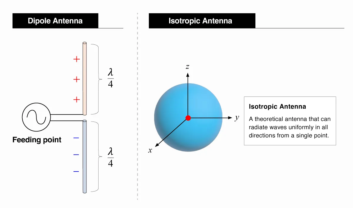
An explanation will now be given with respect to the structure of the simplest antenna system, a dipole antenna.

In a dipole antenna system, a set of two metallic rods each having a length of 1/4λ(λ = wavelength) functions as antennas. Antennas that have better conversion efficiencies from electric signals to radio waves tend to be of a size (length) that is a half (1/2) or a quarter (1/4) of the wavelength. The shorter the wavelength is, the smaller the antenna can be. The wavelength is the value of the speed of light divided by the frequency (i.e., the inverse number of the frequency). Therefore, it is possible to make the antenna smaller the higher the frequency becomes.

The efficiency of an antenna is represented by the term “gain.”

If an antenna that has no size is imagined, in this case, the directions in which the radio waves are radiated (hereafter referred to as a radiation pattern) would become every direction across 360 degrees. In other words, the radiation pattern would become a perfect sphere. An antenna with a radiation pattern of a perfect sphere (which does not exist in reality) is called an isotropic antenna, and is considered as a standard for antenna gain.

Actual antennas have physical sizes, meaning that their radiation patterns are distorted. When it is said that a radiation pattern is losing shape, this means that there is an imbalance in the energy that is being radiated from an antenna.

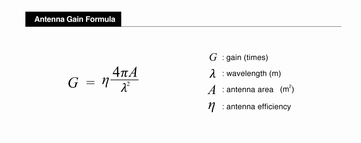
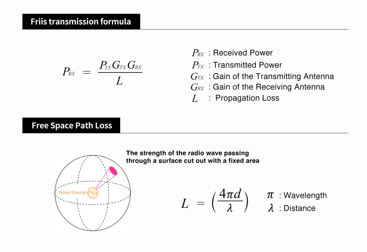
When the energy becomes uneven, the energy density becomes higher in comparison to that of the isotropic antenna. “Antenna gain” is a value that indicates how much higher the energy is in comparison with the isotropic antenna. Antenna gain can be calculated based on the following formula.

Basically, antenna gain can be increased by limiting the directions in which energy is radiated. This is referred to as “increasing the antenna’s directivity.” In other words, antennas with greater gain have higher directivity.

Additionally, the formula for antenna gain also indicates that the larger the antenna’s area is in relation to the wavelength, the greater the entire antenna gain will become. By using higher frequencies, such as millimeter and terahertz waves, which have not been used in traditional communication services, antennas can be extremely small. This means that the same antenna area as before can easily produce greater gains.

Meanwhile, the antennas that have been used up until now for smartphone communications have been very small. In fact, in the frequency ranges that have been used up until now, these antennas have a similar radiation pattern to that of the isotropic antenna.

However, as higher frequencies are used, antennas as small as those installed inside smartphones can also be made to have directivity. Antennas with directivity can lead to deterioration in communication quality, depending on the direction of the antenna (i.e., how the smartphone is held). Therefore, in order to realize efficient communications, it is important to know the direction of arrival (DOA) for the radio waves.

Utilization of a Rotating Reflector Antenna

The Research Institute of Advanced Technology has developed a “rotating reflector antenna” as a technology to measure the DOA of millimeter waves.

The rotating reflector antenna was developed by applying a technology of measuring the DOA of radio waves by using parabolic antennas with a very high directivity. This technology takes advantage of the characteristics of parabolic antennas, in which the directivity increases proportionally to the gains, and performs a 360-degree scan with a beam to measure the DOA of the radio waves.

You may have seen parabolic antennas rotating at airports or other locations. As the rotation for performing scans using these parabolic antennas causes friction, they cannot be rotated at a high speed.

The rotating reflector antenna developed by the Research Institute of Advanced Technology only rotates the parabolic reflector part instead of the antenna itself, making it possible to rotate the antenna without creating friction. (It rotates at up to 10 times per second)

By using the rotating reflector antenna, the DOA of radio waves can be scanned in all directions in almost real time. In addition, by applying the rotating reflector antenna to terahertz, we can increase only the frequency while still using the same size of antenna, and thus improve antenna gains. (A tenfold increase in frequency brings about a hundredfold increase in the gain)

Conversely, terahertz waves have incredibly short wavelengths, which means that if the amount of gains are the same, the size of the antennas can be reduced. This increases the possibility of practical implementation in realistic sizes, even for special antennas that require extremely large aperture sizes.

Measuring the Propagation Properties of the Terahertz Band

A calculation called the “link budget” is performed when communication areas are built with radio waves. This is also known as the circuit design and is an extremely important process during the construction of wireless communication areas.

One of the formulas that indicate radio propagation is the “Friis Transmission Equation (Formula Y)”. In this formula, the received power is calculated by multiplying the power of the transmitted wave, the gain of a transmitting antenna, a propagation loss, and the gain of the receiving antenna. When the transmitted power and the gains of both the transmitting and receiving antennas are invariable, the propagation loss of the space can be calculated by measuring the received power.

However, in reality, the ultimate received power is measured taking various factors into consideration. This is because the propagation loss in space is affected by many factors in addition to free-space propagation losses (i.e., the pure loss of radio waves in a vacuum). These include influences caused by the atmosphere, rain, and reflection, as well as fluctuations caused by the passing of vehicles, and effects caused by the shadows from buildings.

In some cases, factors other than the pure propagation loss in a vacuum need to be considered, while in other cases, they do not. Due to this, if wireless communication areas are constructed without considering all factors, problems can arise such as an interruption in communications when a vehicle passes by or losing reception after turning at an intersection.

To avoid these problems, these factors need to be considered in the form of, for example, a “rain margin” or a “fading margin.” To determine what values should be set for these margins, it is imperative to analyze the data collected through repeated experiments.

The radio waves that are used for smartphones have been used for over twenty years, during which time a large volume of data has been collected. On the other hand, there is almost no data available that is required for the development of new frequencies.

The Research Institute of Advanced Technology has been conducting verification tests through various experiments to calculate the above-mentioned “link budget.”

  • Link budget: The acceptable loss, which is calculated by totaling all of the gains and losses on the transmitting side and receiving side of a signal path.

Research and Tests Carried out by the Research Institute of Advanced Technology

Up until now, we have been conducting these verification tests in an indoor anechoic chamber that is not affected by external elements. However, experiments in confined spaces such as an anechoic chamber cannot sufficiently verify the properties of propagation.

This is why in August 2022, we obtained an experimental radio station license for the terahertz band and began the verification of the propagation properties of radio waves in actual environments. These experiments include measurements taken in a hallway at the SoftBank headquarters building, as well as experiments conducted in outdoor environments.

The photo below shows that the reception of radio waves was confirmed in what is called an “over-the-horizon” environment, in which the transmitting antenna cannot be seen from the receiving antenna. This image also shows that the DOA of these radio waves is distorted by the streetlight pole.

While the measurement of the DOA of radio waves has often been verified for lower frequencies, SoftBank was the first to achieve such verification in the terahertz band. This verification was made possible by the development of the rotating reflector antenna.

Communication infrastructure has already become an integral part of people’s lives. It plays a role not just in smartphone communications, but also as a part of the social infrastructure that supports various industries.

The commercialization of 6G is being pursued with the goal of around 2030. By then, communication traffic demand is expected to grow to nearly 100 times the current level. The R&D of communication technologies is also progressing in response to changes in society. In a world where communication infrastructure supports industries more than ever, the need for high-speed and stable communications are expected to increase.

Furthermore, it is also expected that new businesses will emerge as a result of the realization of these high-speed, stable communications. The exploration of the terahertz band and its effective utilization will play a significant role in achieving these high-speed, stable communications.

The Research Institute of Advanced Technology will continue its R&D activities for the terahertz band, with the aim of achieving stable, ultra-high-speed and low-latency mobile networks as a social infrastructure.

Toward the Creation of a Robust and Scalable Mobile Network

Next

Research Areas