Contents
- Blog
- Wireless, Computing
Let’s Try Quantum Annealing ~ Array Antenna Design Using Quantum Computers ~
#6G #QuantumTechnology #QuantumAnnealing #QuantumComputers #ArrayAntenna
Jan 16, 2026
SoftBank Corp.
Topics
1. Antenna Design Using Quantum Computers
We have conducted research on applying quantum computers to antenna design. As shown in Table 1, current computers can be classified into conventional digital computers and quantum computers. Quantum computers are further divided into gate-based and Ising-based approaches. The Ising model approach is a quantum computer specialized for combinatorial optimization problems. Conventional digital computers can be divided into CPU-type, which are general-purpose processors, and accelerator-type, which incorporate accelerators such as GPUs or vector processors.
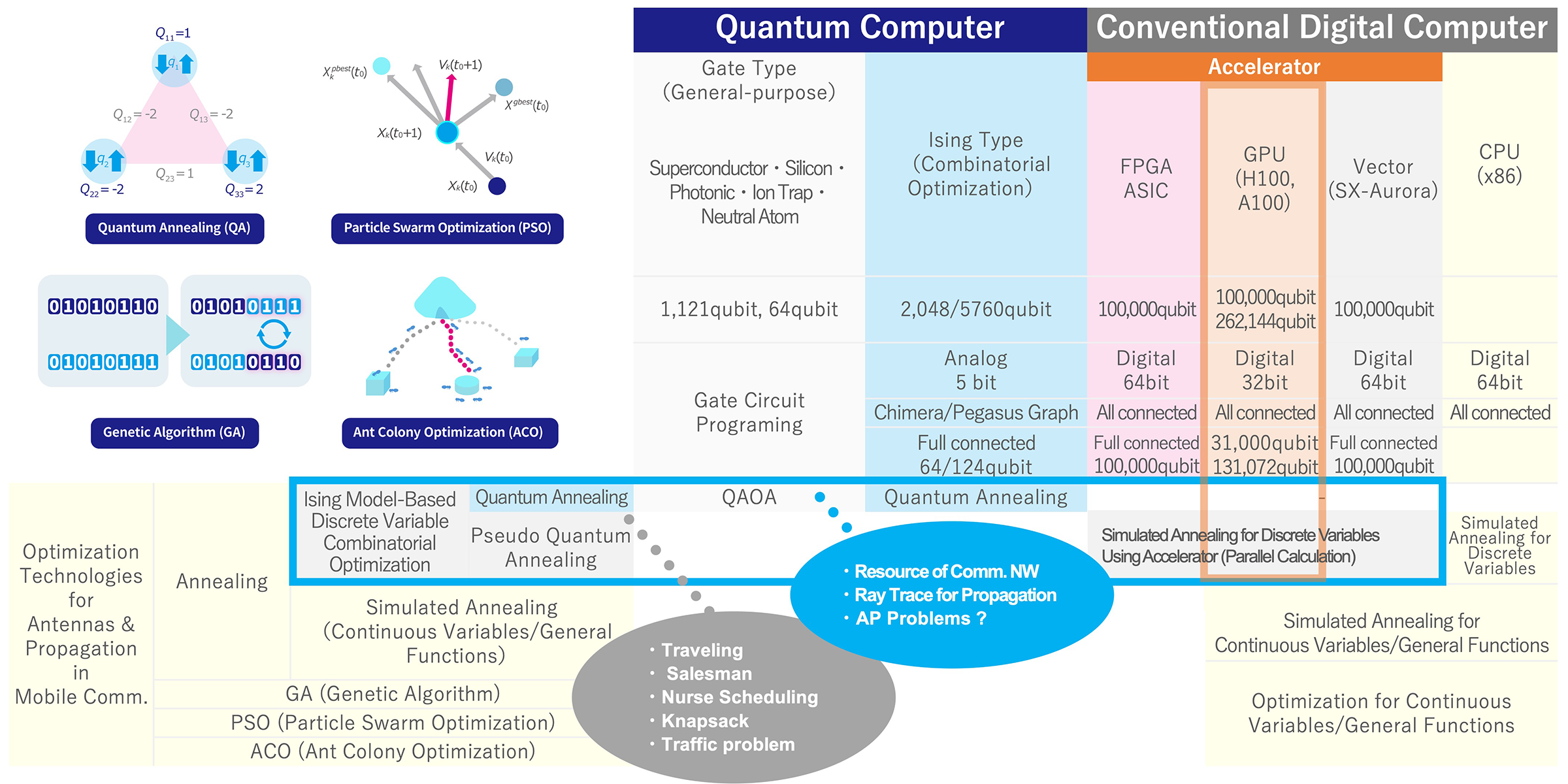
Table 1. Optimization and Quantum Computer
Various optimization methods are employed in antenna design and many other scientific computations. Techniques such as annealing, genetic algorithms (GA), particle swarm optimization (PSO), and ant colony optimization (ACO) are utilized. While genetic algorithms are widely used for antenna design optimization, computational complexity increases significantly with the number of variables due to combinatorial explosion.
Figure 1 illustrates an example of combinatorial explosion in antenna design optimization. Consider the case of mounting an antenna on an automobile body. The problem is to find the location where the received power is statistically and on average highest, given 300 candidate antenna mounting locations. In general, this can be solved by installing an antenna at each of the 300 locations, performing 300 electromagnetic field calculations, and then identifying the antenna location with the highest average received power.
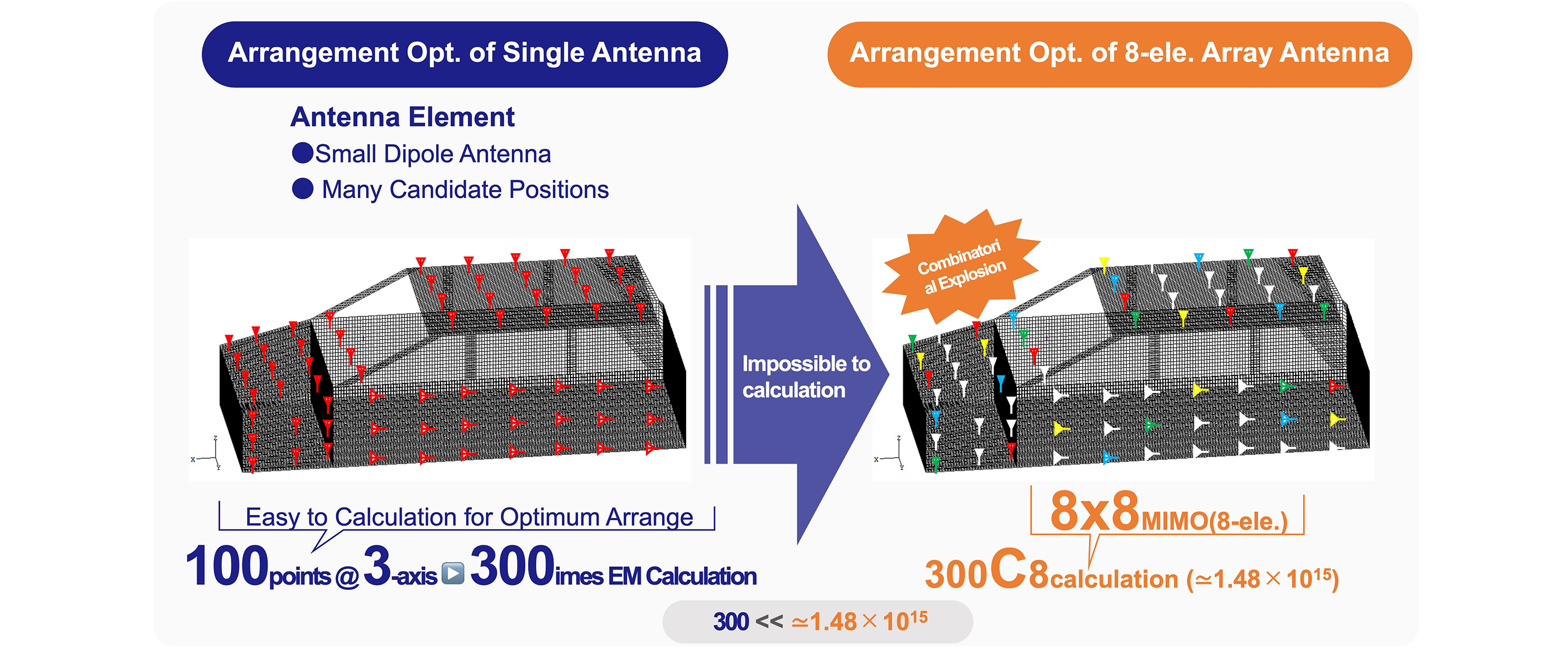
Figure 1. Combinatorial Explosion (Vehicle Antenna)
Next, consider installing 8 antennas at 300 candidate locations. Because antennas are interdependent, selecting the top 8 antennas by received power does not necessarily yield the maximum power. Therefore, it is necessary to calculate all combinations of 8 antennas to maximize the average received power. The number of combinations for this antenna calculation is 300C8 ≃ 1.48×10¹⁵ resulting in an extremely enormous computational load. This can be considered an infeasible problem.
Against this backdrop, this blog demonstrates that quantum annealing enables efficient antenna design optimization where conventional computational methods fail. As a concrete example, an optimal design method for multi-beam generation in array antennas is presented. This method involves refining the quantization of feed phase and devising a constraint term for stable multi-beam generation.
2. Quantum annealing
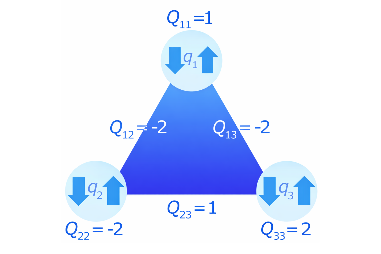
Here, we will briefly outline quantum annealing using a minimal model. Quantum annealing is modeled using spins in a magnetic material (the orientation of the north poles of tiny magnets), as shown in Figure 2. The orientation of the tiny magnet is treated as a quantum bit, where pointing up is +1 and pointing down is -1. A quantum annealing machine is a physical emulator that operates to minimize the energy of the magnetic material. Solving the problem is equivalent to determining the orientation of the tiny magnets that minimizes the total energy of the system when three such magnets are arranged.
Here, the system is modeled in Ising form. Each individual magnet has a tendency to align either upward or downward, referred to as its self-action (hi). Meanwhile, each magnet interacts with others, exhibiting an interaction (Jij) that causes them to either align in the same direction or in opposite directions. In the diagram, the system is defined by the following conditions:
① Self-action h1 of magnet 1: +2 (desire to point downwards, strength 2)
② Self-action h2 of magnet 2: +1 (desire to point downwards, strength 1)
③ Self-action h3 of magnet 3: -3 (desire to point upwards, strength 3)
④ Interaction J12 between magnet 1 and 2: +2 (desire to be opposite, strength 2)
⑤ Interaction J23 between magnet 2 and 3: -2 (desire to align in the same direction, strength 2)
⑥ Interaction J13 between magnet 1 and 3: -2 (desire to align in the same direction, strength 2)
If only self-interactions acted in this system, magnet 1 and 2 would align downward, and magnet 3 would align upward. However, since interactions also exist within the entire system, the above six conditions cannot all be satisfied simultaneously, resulting in a “frustrated state.” At this point, the effectiveness of the conditions changes depending on the strength of each interaction. This can be expressed as a three-variable quadratic function in the energy equation.
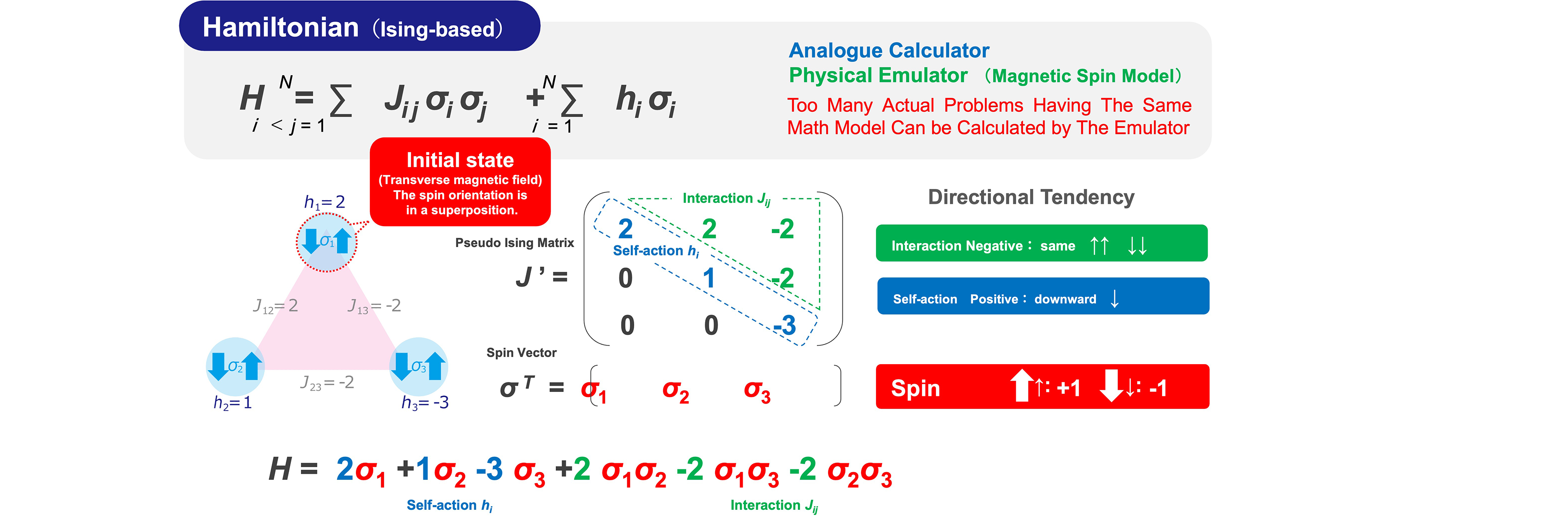
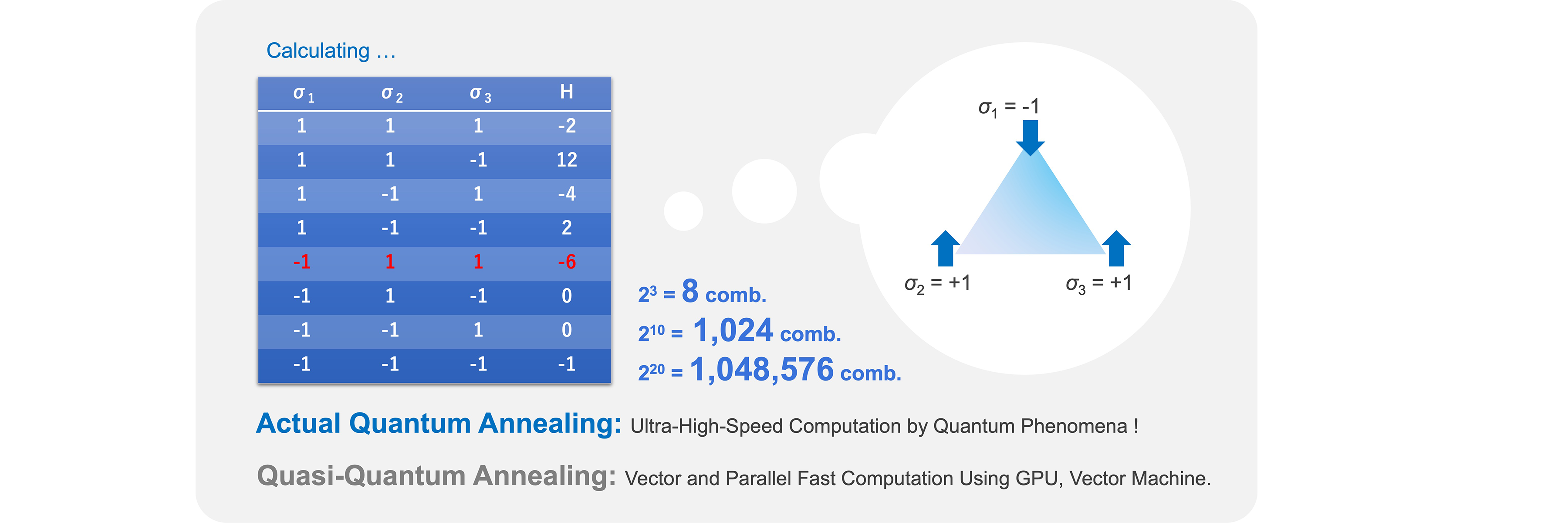
Figure 2. Quantum Annealing (3-Qubit)
Entering this equation into a quantum annealing machine sets the self-interactions and interactions between qubits. The machine then “leaves it to nature” to perform operations that minimize energy, returning the qubit values and energy values at that point as the answer. Unlike conventional computers, programming is unnecessary; setting these interaction coefficients itself constitutes the programming.
This time, with only 3 qubits (variables), there are 8 possible combinations. Calculating them by hand yields the table in Figure 2. As a result, we see that the energy is minimized when:
σ1 = -1, σ2 = +1, σ3 = +1, H = -6
Let's try changing the self-action and interaction values in the Excel demo software and observe how the results change!
Download the trial Excel file here.
Here is a specific application example of this mathematical model. Three people are planning a trip. Quantum bits are assigned as follows: -1 for Kamakura and +1 for Hakone. Each individual's preferred destination and preference level are:
① Person A's preference for Kamakura: 2
② Person B's preference for Kamakura: 1
③ Person C's preference for Hakone: 3
Their mutual preferences for traveling together are:
④ A and B's desire to go to a different place: 2
⑤ B and C's desire to go to the same place: 2
⑥ C and A's desire to go to the same place: 2
This travel schedule problem is mathematically equivalent to the aforementioned magnetic energy problem. In other words, if all problems in the world can be reformulated as magnetic models, then combinatorial optimization problems as social issues can be efficiently solved using quantum annealing machines.
3. Multi-Beam Synthesis Method of Array Antenna
Here, an application example of a multiple beam synthesis and design method for array antennas is presented. This research was published as a letter in the Institute of Electronics, Information and Communication Engineers journal ComEX [1], as a result of joint research between the Research Institute of Advanced Technology, SoftBank and University of Fukui (Professor Mitoshi Fujimoto). The key points of this technology are: (A) converting the complex exponential function used for array antenna feed phase into a linear function via one-hot encoding, and (B) devising an additive Hamiltonian formulation to stably generate multiple beams with equal gain.
Technology(A) : Linearization of Complex Exponential Functions via One-hot Encoding
In quantum annealing, the Hamiltonian is formulated as a quadratic function of quantum bits. In antenna radiation directivity design, the Hamiltonian effectively corresponds to power, so the electric field must be expressed as a linear function. On the other hand, electromagnetic field analysis methods are used for antenna design, necessitating vector synthesis using phase, which requires the complex exponential function. Therefore, converting the complex exponential function into a linear function is essential for performing vector synthesis, such as radiation pattern synthesis, using quantum annealing. To achieve this, linearization was realized using one-hot encoding, as shown in Figure 3.
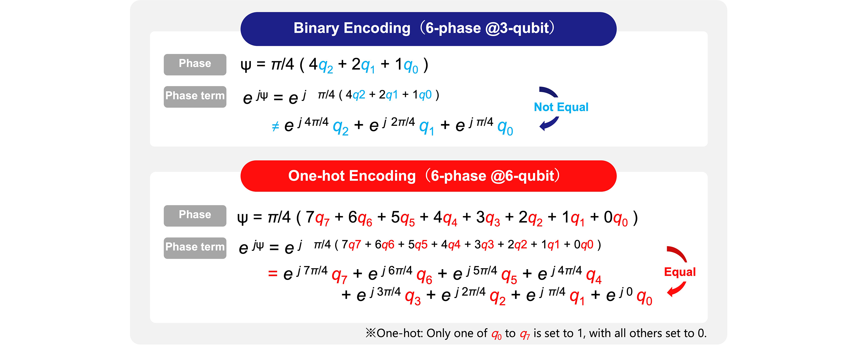
Figure 3. Linearization of Complex Exponential Functions via One-hot Encoding
Technology(B) : Formulation of Constraints for Multi-Beam Synthesis
In quantum annealing, satisfying multiple conditions can be achieved by describing the Hamiltonian each condition must satisfy and adding them together. Figure 4 shows a computational example (N = 40, M = 4) where the Hamiltonian was set using a model that concentrates power in the -10° and 40° directions by appropriately assigning M-level phases to an N-element array antenna. In the conventional method shown in Example (a), only a single beam is generated, concentrated in one direction, rather than two beams. Analysis revealed that generating a single beam result in a smaller Hamiltonian compared to generating multiple beams. Therefore, as shown in Example (b), a new constraint term (red box) was added to ensure the specified number of beams is generated. This constraint term minimizes the power difference between multiple beams. The calculation results applying this constraint are shown. It was confirmed that beams were generated at -10° and 40° with no gain difference. This demonstrates that quantum annealing is effective for array antenna multi-beam design when using the proposed technique.
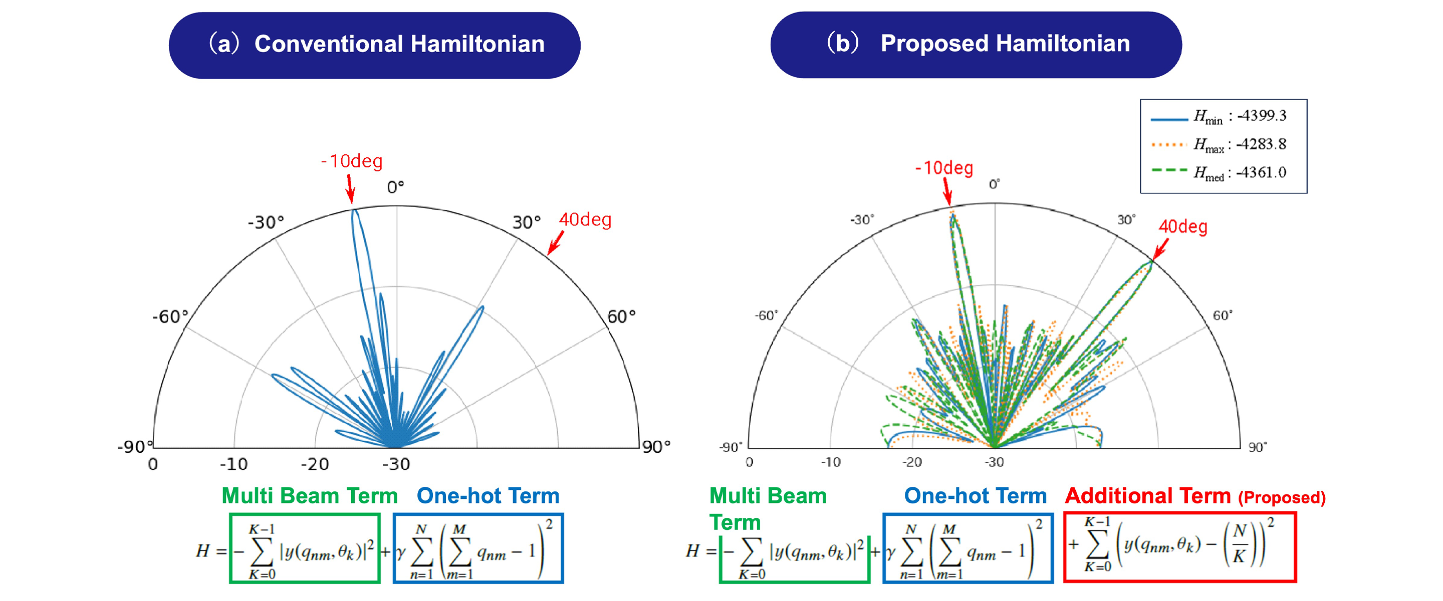
Figure 4. Multi-Beam Synthesis of Array Antenna
4. Overview of Application Areas
In this blog, we presented an example of array-antenna design; however, the same approach can also be applied to designing elements of RIS (Reconfigurable Intelligent Surfaces) [2], which steer reflected waves by imposing phase variations on the surface.
Moreover, because the linearization of complex exponential functions can be broadly applied to wave engineering, we believe its potential application areas extend widely—not only to electromagnetic-field problems such as EMC (ElectroMagnetic Compatibility) and microwave technologies, but also to many other related fields.
References
[1] Kayako Yuda, Mitoshi Fujimoto, Ryo Yamaguchi, Kazuma Tomimoto, and Tomonori Ikeda, "Multiple beamforming of array antenna using quantum annealing," IEICE Communications Express, Vol. 14, No. 12, pp. 1-4, Dec. 2025.
[2]Realization of Base Station Antennas Using RIS Technology and the Characteristics of RIS Antennas,
https://www.softbank.jp/en/corp/technology/research/topics/112/, October,2024.