Verification of Outdoor Area Coverage Using Functional Beam Shaping Lens Antenna

#6G #MassiveMIMO

1. Simplification of base station antennas through the application of metasurface lens technology

To accommodate the ever-increasing volume of communication traffic, commercial services utilizing frequencies with wide bandwidths, such as mm-wave band, have been launched since the commencement of 5G (5th generation mobile communications) services [1]. As frequency increases, the distance over which radio waves can propagate decreases. Therefore, base station antennas require a configuration that not only amplifies the radio waves emitted from the antenna but also incorporates a “beamforming” function capable of tracking the user's direction of movement.

To meet these requirements, base station antennas must adopt massive element array antennas equipped with numerous control ICs (integrated circuits) to manage signal strength and radiation direction. However, such antenna configurations face challenges: increased element count and control ICs lead to larger, more complex circuits and higher power consumption [2]. To resolve these issues, simplifying the antenna configuration while considering radio wave propagation characteristics is crucial.

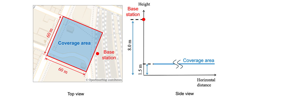
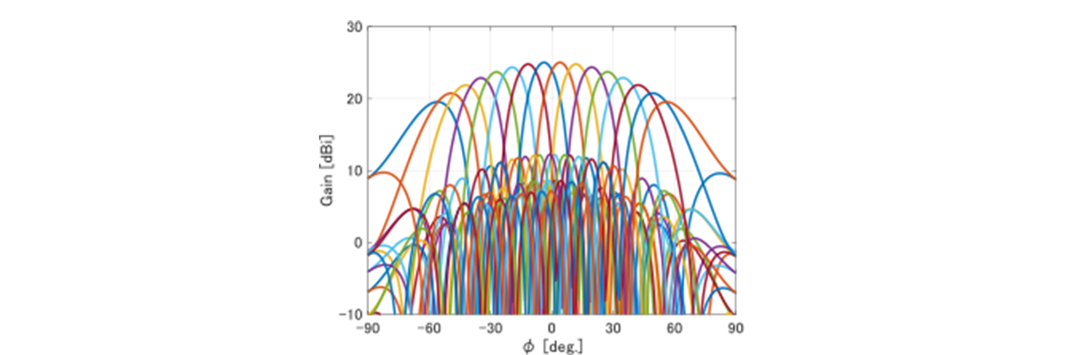
Focusing on the movement tendencies of UE(user equipment), it is known that while movement occurs frequently in various horizontal directions relative to the base station, vertical movement is limited [3]. This characteristic led to the idea that “while beamforming technology is essential for the horizontal direction, the vertical direction might be handled without beamforming, potentially forming the communication area by carefully designing the antenna beam.”

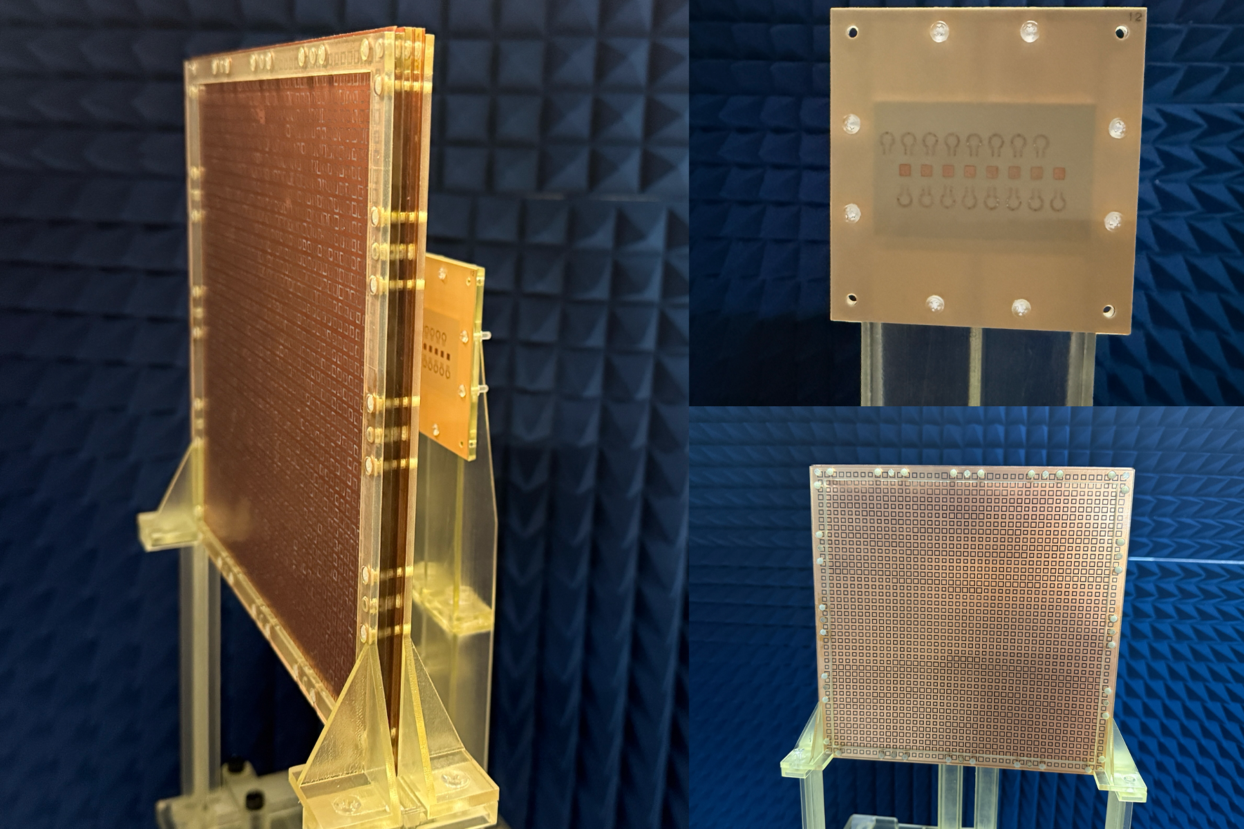
Aiming to simplify the antenna configuration, we focused on the “lens antenna (transmit array antenna),” which places a metasurface lens near the antenna. While this antenna configuration increases volume, it offers the advantage of amplifying radiated waves and enabling diverse antenna beams using fewer antenna elements and control ICs. Furthermore, the metasurface lens can be placed on surfaces like the rear of a radome, eliminating the need for significant modifications to existing base station structures. Therefore, if antenna patterns enabling communication area formation can be realized using metasurface lens technology, it is considered possible to achieve a simplified, low power antenna configuration. This would eliminate the need for vertical beamforming via control ICs, which was required in conventional base station antennas.

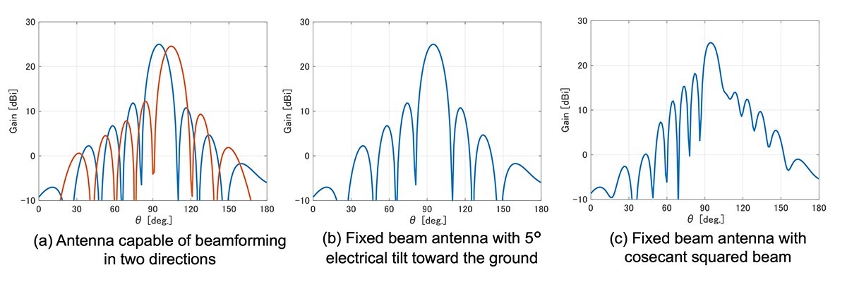
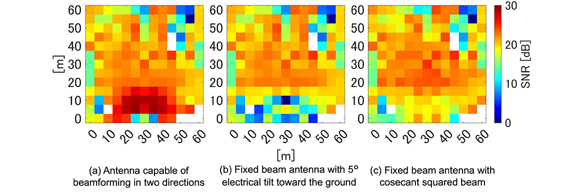
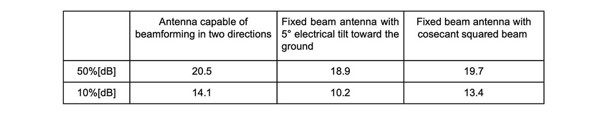
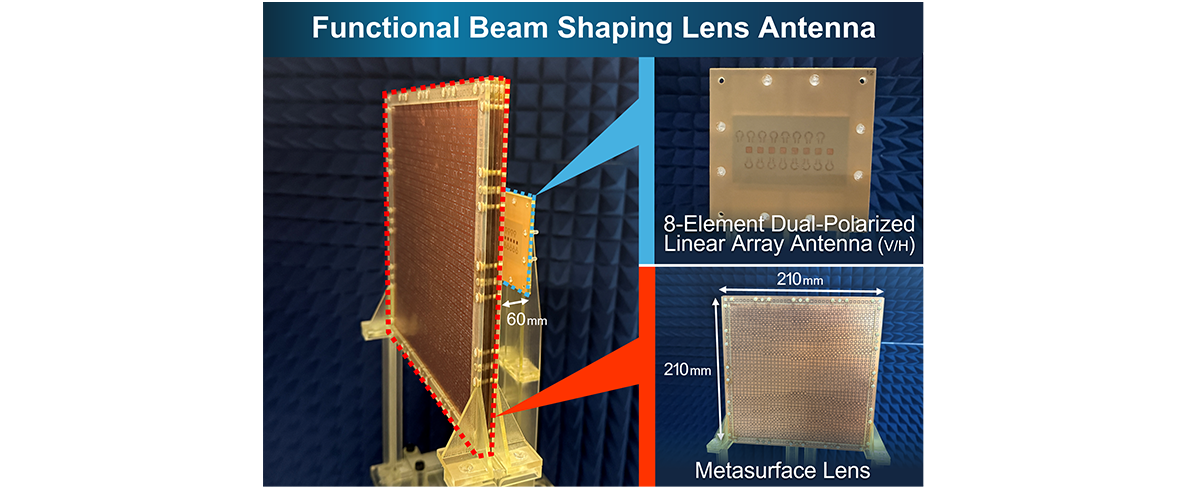
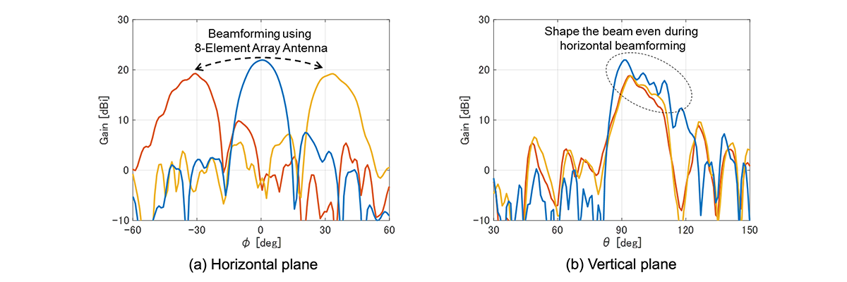
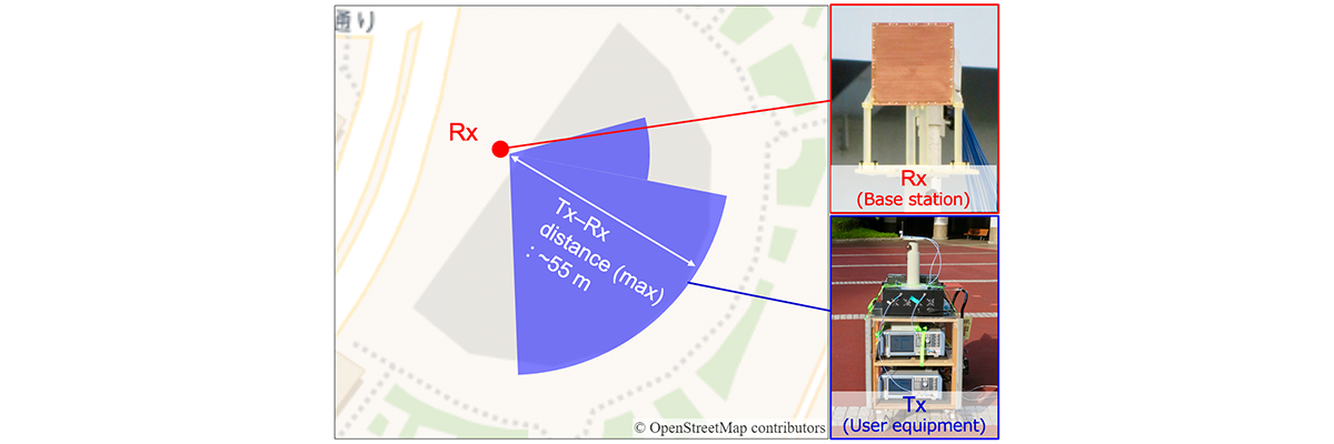
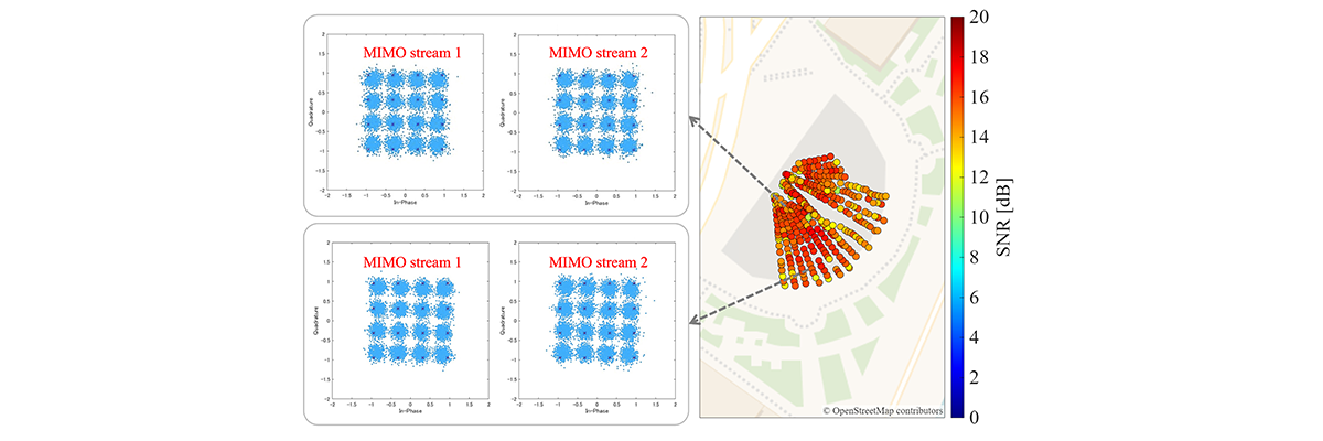
This article presents the results of an investigation aimed at reducing the number of antenna elements and control ICs in the vertical direction by applying AGC Inc. metasurface design technology to base station antennas. Specifically, through area simulation, we evaluated differences in characteristics due to antenna beams and demonstrated that a communication area can be formed without relying on beamforming in the vertical plane by realizing an antenna beam with a cosecant squared beam. Furthermore, we prototyped “Functional Beam Shaping Lens Antenna” that achieves radiation characteristics resembling a cosecant squared beam. We describe the results of evaluations conducted in outdoor environments, demonstrating the effectiveness of this technology.

Concept of development

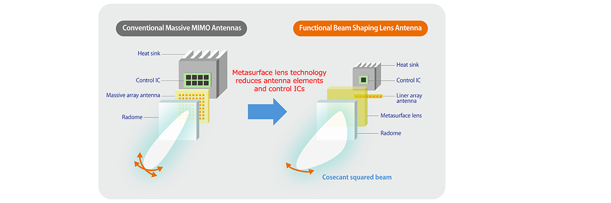
Figure 1. Concept of development

2. Area Simulation ~Outdoor Hotspots~

To verify whether communication areas can be formed without relying on vertical beamforming, area simulations were conducted using NVIDIA Sionna [4]. Figure 2 shows the simulation area. This simulation evaluates the SNR (Signal-to-Noise Ratio) characteristics within a 60m×60m reception area at the Shimbashi Station in Tokyo, Japan, simulating an outdoor hotspot environment with concentrated communication traffic. Figure 3 shows the vertical antenna beam characteristics used for the base station antenna. For the vertical beam characteristics, we examined the following three options:

・Antenna capable of beamforming in two directions
・Fixed beam antenna with 5° electrical tilt toward the ground
・Fixed beam antenna with cosecant squared beam*

Note that the horizontal plane is assumed to be capable of beamforming within the range of -60° to 60°, as shown in Figure 4.

*Cosecant squared beam: An antenna beam that compensates for signal attenuation with distance, aiming to make the received power as uniform as possible from the vicinity of the base station to distant locations.

Simulation area

Figure 2. Simulation area

Antenna beam characteristics for base station antenna (vertical plane)

Figure 3. Antenna beam characteristics for base station antenna (vertical plane)

Antenna beam characteristics for base station antenna (horizontal plane)

Figure 4. Antenna beam characteristics for base station antenna (horizontal plane)

Figure 5 shows the area simulation results for each beam characteristic. Additionally, Table 1 shows the cumulative distribution function (CDF) values at 50% and 10% used as indicators for area coverage improvement. From Figure 5, the antenna capable of beamforming in two directions can direct the beam almost precisely toward the user's location. Therefore, compared to other beam characteristics, it has a wider overall high SNR area and the best area characteristics. Next, the fixed beam antenna with a 5° electrical tilt toward the ground exhibits high SNR at locations where the distance between base stations and UE is large. Conversely, at locations where the distance is small, SNR frequently drops to around 0 dB. Next, the fixed beam antenna with a cosecant squared beam does not experience extreme SNR drops even in locations with closer base station and UE distances, forming a more stable reception area. Table 1 shows that the fixed beam antenna with a cosecant squared beam maintains differences within 1 dB for both the 50% value and 10% value compared to antennas capable of beamforming in two directions. Therefore, if such an antenna with this beam pattern can be realized with a simple structure, it may be possible to achieve area coverage close to that of conventional Massive MIMO antennas while reducing base station operating costs.

Area simulation results

Figure 5. Area simulation results

Comparison of CDF values at 50% and 10%

Table 1. Comparison of CDF values at 50% and 10%

3. Prototype of Functional Beam Shaping Lens Antenna Achieving Vertical Beam Shaping

To simplify base station antenna configurations, we collaborated with AGC Inc. to design and develop a functional beam shaping lens antenna utilizing a metasurface lens. Figure 6 shows the functional beam shaping lens antenna developed by AGC Inc., and Figure 7 shows its radiation characteristics. Figures 6 and 7 demonstrate that the functional beam shaping lens antenna achieves beamforming in the horizontal plane using an 8-element array antenna and exhibits radiation characteristics in the vertical plane that resemble a cosecant squared beam.

This antenna enables area coverage without requiring beamforming in the vertical plane, allowing for a reduction in the circuitry needed to control the beam direction. Compared to a Massive MIMO antenna achieving the same coverage area, the developed functional beam shaping lens antenna requires one-eighth the number of antenna elements and reduces the number of control ICs. Consequently, when estimating power consumption using the control IC from Reference [5], the Massive MIMO antenna consumes approximately 50W, whereas the developed antenna is expected to reduce power consumption to about 6W. Furthermore, the significant reduction in power consumption is expected to decrease heat dissipation from the control IC, potentially allowing for lighter heat sinks required for heat removal.

Functional Beam Shaping Lens Antenna

Figure 6. Functional Beam Shaping Lens Antenna

Radiation characteristics of development antenna

Figure 7. Radiation characteristics of development antenna

4. Outdoor Measurement Evaluation Using 5GNR Signal

To evaluate whether stable communication areas can be formed when using the developed antenna, measurements of SNR characteristics and MIMO transmission characteristics using 16QAM were conducted in an outdoor environment. Figure 8 shows the measurement site. We performed the evaluation using a 5GNR signal evaluation system [6] built by combining general-purpose measuring instruments, configured for the uplink processing system. The developed antenna was installed at a height of approximately 8 meters as the base station antenna. A dipole antenna was used as the UE antenna, and measurements were performed while moving. The UE antenna transmits two streams of 5G NR(New Radio) uplink signals at a radio frequency of 29.7 GHz and a bandwidth of 100 MHz. Data received by the developed antenna was transferred to the control PC via an array receiver. Horizontal beamforming processing was performed within the control PC. Demodulation processing was then applied to the beamformed data to obtain the SNR and the constellation characteristics of the MIMO streams.

Figure 9 shows the results of outdoor measurements using the developed antenna. The points in the figure indicate the SNR values at each measurement location, with redder colors representing higher SNR and bluer colors representing lower SNR. Using the developed antenna yielded high SNR overall, confirming stable SNR characteristics across the entire measurement area, independent of the distance between the receiving and transmitting antennas. Next, two points were randomly selected from locations near and far from the base station. The received MIMO streams were demodulated, and the symbol points were plotted. The results confirmed that both streams clustered into 16 distinct locations. This closely matches the ideal symbol point positions for 16QAM, demonstrating the feasibility of data transmission using MIMO technology. Consequently, the functional beam shaping lens antenna can provide a stable communication area while reducing the number of components.

Measurement site

Figure 8. Measurement site

Outdoor measurement result

Figure 9. Outdoor measurement result

5. Future Outlook: Reducing Base Station Operating Costs and Deployment Complexity

This study presents results aimed at reducing the number of antenna elements and control ICs in the vertical direction by applying lens antenna technology to base station antennas. The developed functional beam shaping lens antenna holds potential to contribute to reductions in power consumption and weight while achieving area coverage comparable to Massive MIMO. Consequently, it is expected to contribute to lowering base station operating costs and reducing installation complexity. Furthermore, it is anticipated to reduce the overhead associated with beam search, a challenge in beamforming antennas [7]. Moving forward, we plan to conduct outdoor verification by connecting the developed antenna to actual base station equipment and advance further studies toward societal implementation.

Reference

[1] Ericsson, “Leveraging the potential of 5G millimeter wave,” 2018.
[2] F. Rusek et al., "Scaling Up MIMO: Opportunities and Challenges with Very Large Arrays," in IEEE Signal Processing Magazine, vol. 30, no. 1, pp. 40-60, Jan. 2013.
[3] 3GPP, “Study on channel model for frequencies from 0.5 to 100 GHz,” TR 38.901 (Rel. 18), V18.1.0, 2025.
[4] NVIDIA Corporation, Sionna, https://developer.nvidia.com/ja-jp/sionna
[5] Analog devices,ADMV4828, https://www.analog.com/jp/products/admv4828.html
[6] S.Tabuchi, et.al,. “Construction of a Multi-Antenna Evaluation System Using 3GPP-Compliant Signals,” 2025 International Symposium on Antennas and Propagation(ISAP), Fukuoka Japan, October 2025.
[7] W. Attaoui, K. Bouraqia and E. Sabir, "Initial Access & Beam Alignment for mmWave and Terahertz Communications," in IEEE Access, vol. 10, pp. 35363-35397, 2022.

Research Areas
研究概要