Contents
- Blog
- Wireless, HAPS
【Part 2】 How Optical Wireless Communication Can Enable NTNs — Extending Connectivity Beyond the Atmosphere
#HAPS #NTN #OpticalWirelessCommunication
Jul 24, 2026
SoftBank Corp.
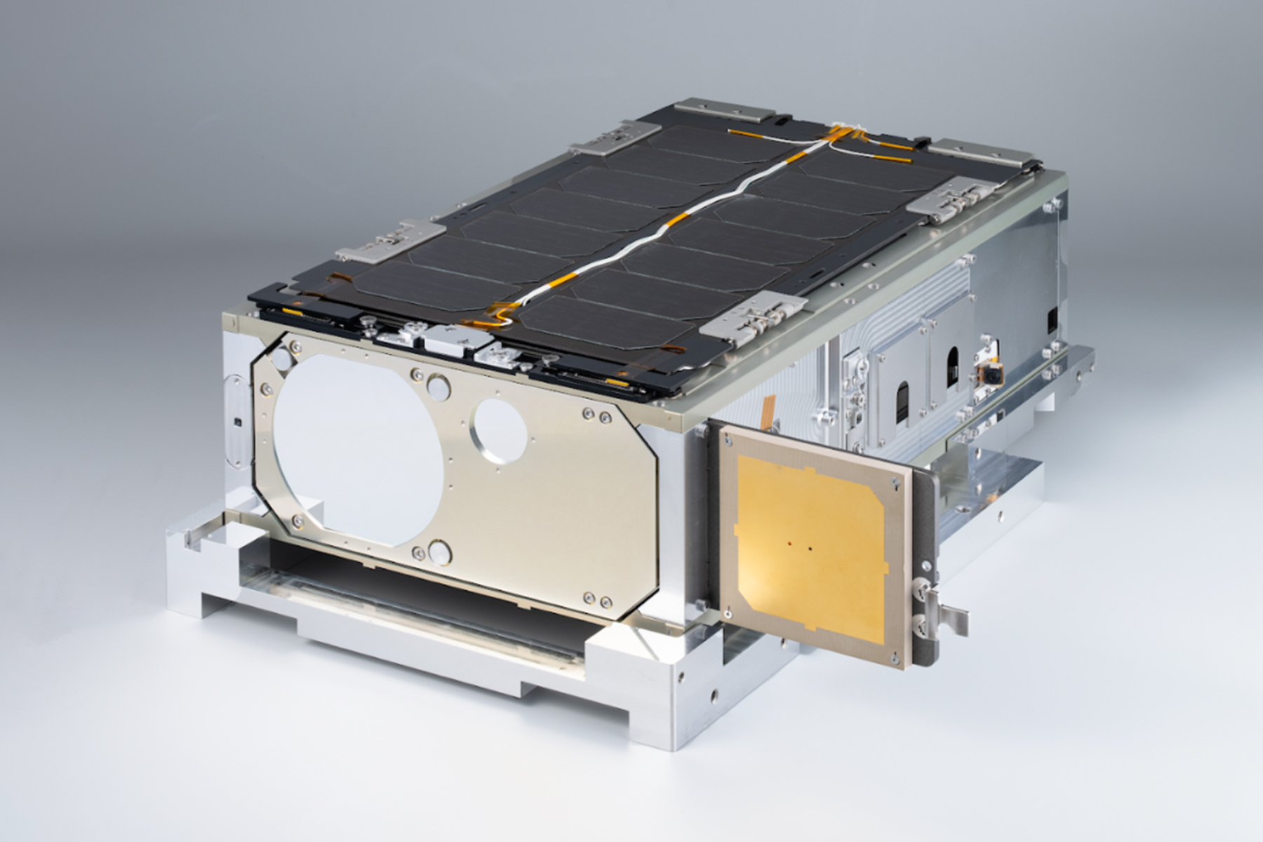
In Part 1, What Is Optical Wireless Communication for Space and the Stratosphere? A Beginner-Friendly Introduction, we introduced the basics of optical wireless communication. We explained how it differs from fiber-optic communication and radio communication, how it works, and some of the demonstration experiments that have been carried out so far.
In Part 2, we'll look at what kinds of Non-Terrestrial Network (NTN) systems can already be built using today's optical wireless communication technology. We'll also explore what the future may hold as the technology continues to advance.
1. Understanding Optical Wireless Communication Through Link Budget Analysis
One of the biggest advantages of optical wireless communication is its ability to deliver highly concentrated energy to the receiving end. This becomes clear when we look at the link budget.
A link budget is a method used to estimate whether a communication system can deliver a signal that is strong enough to be received successfully. It does this by adding up all the gains and subtracting all the losses that occur as the signal travels from the transmitter to the receiver.
A signal is considered strong enough if its received power is above the minimum level required for reliable communication. This minimum level is determined mainly by the performance of the optical detector used in the receiver.
The difference between the estimated received power and the minimum required power is called the margin. In communication systems, a margin of at least 3 dB is commonly used to ensure stable and reliable operation.
Equation (1)
Pr [dBm] = Pt + Gt − Lt − Lfs − Latm − Lmisc + Gr − Lr
Received Power = Transmit Power + Transmit Antenna Gain − Transmit-Side Losses − Free-Space Path Loss − Atmospheric Loss − Other Losses + Receive Antenna Gain − Receive-Side Losses
Where:
Pr: Received power
Pt: Transmit power
Gt: Transmit antenna gain
Lt: Transmit-side losses
Lfs: Free-space path loss
Latm: Atmospheric loss
Lmisc: Other losses (such as pointing loss and scintillation loss)
Gr: Receive antenna gain
Lr: Receive-side losses
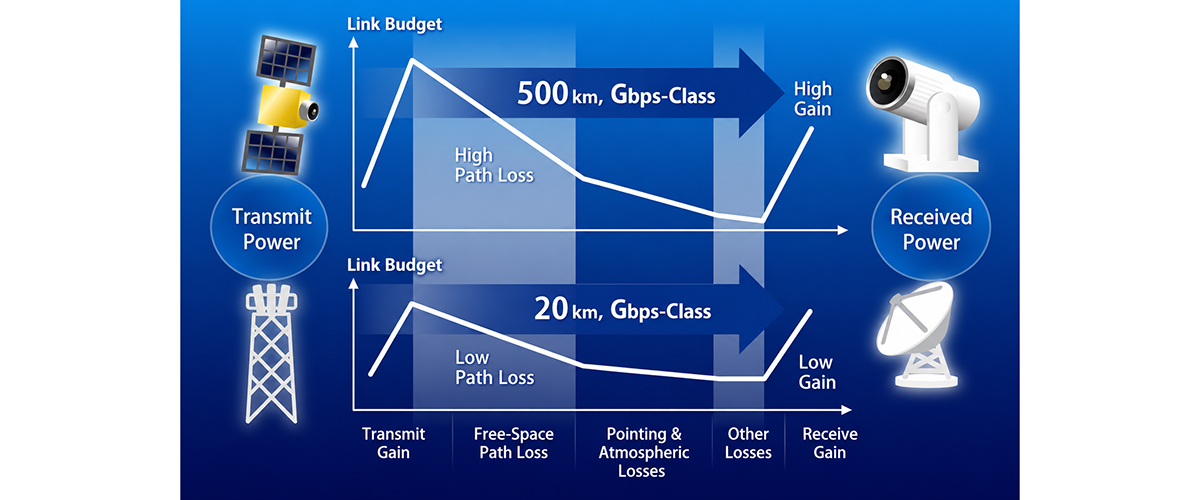
Figure 1. Illustration of a Link Budget
Here, let’s compare the potential transmission capacity of an optical wireless link to that of a microwave link.
As shown in Table 1, we compare two examples: a 23 GHz microwave backhaul entrance link that connects mobile phone base stations using parabolic antennas, and an optical link between a ground station and a low Earth orbit (LEO) satellite.
The link distances are 10 km and 500 km, respectively, and the transmit power is 1 W in both cases.
For readers who are not familiar with dB (decibels), you can think of it as a way of expressing very large differences in power. A difference of 30 dB means 1,000 times, while 40 dB means 10,000 times. In other words, each additional 10 dB adds another zero to the multiplier.
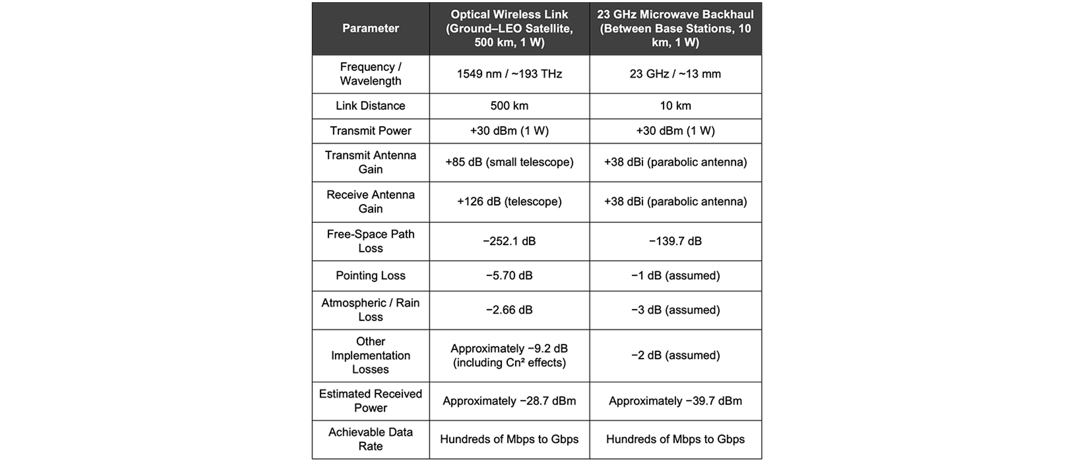
Table 1. Example Link Budget Comparison
In optical wireless communication, the free-space path loss is extremely large—about −252.1 dB in this example. However, because light has an extremely short wavelength (or, equivalently, a very high frequency), optical antennas such as telescopes can provide exceptionally high antenna gain. This is one of the key advantages of optical wireless communication.
In our comparison, the 23 GHz microwave link provides transmit and receive antenna gains of about 38 dBi each. In contrast, the optical wireless link achieves gains of 85 dB on the transmit side and 126 dB on the receive side. These large gains compensate for the much higher path loss. As a result, even over a distance of 500 km, the estimated received power is about −28.7 dBm, comparable to that of a 10 km 23 GHz microwave link.
Although microwave and optical systems use different methods to detect signals, both can support data rates ranging from hundreds of megabits per second to several gigabits per second. This makes them suitable for communication services that can support many users simultaneously.
Interestingly, the ground-to-LEO optical link used in this example is based on results demonstrated by Japan's National Institute of Information and Communications Technology (NICT) using the Small Optical TrAnsponder (SOTA), a compact optical communication terminal carried on a 50 cm-class satellite (Figure 2).
The SOTA experiment actually used a much smaller laser with a transmit power of only 35 mW (15.40 dBm). The experiment used a wavelength of 1549 nm, a satellite altitude of 500 km, a slant range of 1,107 km, and a 1 m ground telescope. The optical system provided approximately 85 dB of transmit gain and 126 dB of receive gain. Even though the free-space path loss reached about 259 dB, additional losses from pointing (5.70 dB), the atmosphere (2.66 dB), and hardware implementation further reduced the signal. The estimated received power was approximately −50.18 dBm, while the measured value was about −51.30 dBm, corresponding to roughly 6 × 10¹⁰ photons per second.
Even at this extremely low power level, the receiver was able to detect individual photons and recover the binary data stream. The SOTA demonstration successfully achieved data transmission at around 10 Mbps. [Reference 1]
These results highlight both the strengths and the challenges of optical wireless communication. The technology is well suited for high-speed data transmission, but it also requires highly accurate pointing and tracking, and its performance can be affected by clouds and atmospheric turbulence.
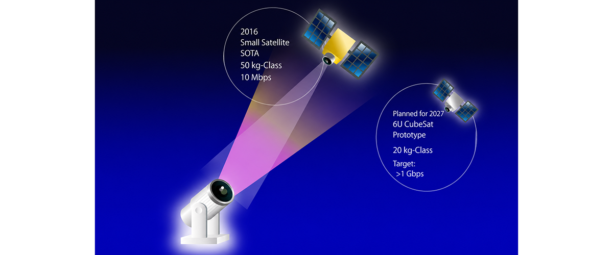
Figure 2. Illustration of the SOTA Satellite and the Smaller CubeSOTA for Ground-to-Satellite Optical Communication
2. Choosing the Right Communication Wavelength
In radio communication, a wide range of frequency bands is used depending on the application. These include the 900 MHz band (33 cm wavelength), often called the platinum band in Japan, as well as 1.5 GHz (20 cm), 2 GHz (15 cm), and higher-frequency bands such as the centimeter-wave and millimeter-wave bands. Each has different propagation characteristics, making it suitable for different use cases.
Optical wireless communication, by contrast, uses wavelengths on the order of micrometers (μm). In this section, we'll look at how these wavelengths are chosen.
From a geometric point of view, shorter wavelengths are advantageous because they allow light to be focused into a narrower beam, increasing antenna gain. However, when light travels through the atmosphere, shorter wavelengths are more strongly affected by atmospheric scattering and absorption. Choosing the right wavelength therefore requires balancing these two competing effects.
The link budget in Equation (1) can be expressed more explicitly using the physical parameters of an optical communication system, as shown in Equation (2).
Equation (2)
Pr = Pt × η × (Dt × Dr / (4 × λ × R))²
Where:
Pr: Received power
Pt: Transmit power
η: Overall optical efficiency (including the transmitter and receiver)
Dt: Diameter of the transmitting aperture (transmitting telescope)
Dr: Diameter of the receiving aperture (receiving telescope)
R: Communication distance
λ: Wavelength
As Equation (2) shows, a shorter wavelength (λ) provides stronger beam directivity, resulting in higher transmit and receive antenna gain. It also reduces the effective free-space path loss. In other words, shorter wavelengths are advantageous from a purely geometric perspective.
For example, if the wavelength is reduced from 1.5 μm to 1.0 μm, while keeping the same telescopes and communication distance, the laser beam spreads less and the received spot becomes smaller. This improves the link budget by about 7 dB, which is roughly equivalent to increasing the transmit power by a factor of five.
However, the situation changes when the communication link passes through the atmosphere, such as in a ground-to-satellite connection.
As light travels through the atmosphere, shorter wavelengths are more susceptible to atmospheric effects. Turbulence causes stronger fluctuations in signal intensity, known as scintillation, while scattering, absorption, and background sunlight during the daytime also become more significant. As discussed later, scintillation caused by atmospheric turbulence scales approximately with λ−7/6, while scattering by aerosols and fog generally follows a negative power of wavelength. In the case of Rayleigh scattering, the dependence is proportional to λ−4. As a result, shorter wavelengths experience greater atmospheric loss.
A familiar example of this effect is a red sunset. As sunlight passes through the atmosphere, the shorter-wavelength blue light is scattered much more strongly than the longer-wavelength red light, leaving the sky with its characteristic reddish color.
This means that shorter wavelengths are ideal for links that remain entirely in space, such as satellite-to-satellite communication. For ground-to-space links, however, reducing the wavelength is not always the best choice because of the additional losses introduced by the atmosphere.
In practice, 1.5 μm and 1.3 μm wavelength bands are the most widely used for optical wireless communication (Figure 3). There are three main reasons for this.
First, these wavelength bands benefit from decades of development for terrestrial fiber-optic communication. As a result, high-quality components, including high-power optical amplifiers, are readily available. The 1.0 μm band is also attracting attention for future systems because it supports high-performance lasers and coherent communication technologies, making it particularly attractive for links that operate mainly in space.
Second, these wavelengths lie outside the visible spectrum, making it easier to design eye-safe communication systems.
Third, they fall within atmospheric transmission windows—ranges of wavelengths where the atmosphere absorbs relatively little light. Although shorter wavelengths suffer more from scattering, atmospheric absorption depends on the molecular composition of the atmosphere and is not simply determined by wavelength alone. The 1.0 μm, 1.3 μm, and 1.5 μm bands all offer relatively high atmospheric transmission, even higher than much of the visible spectrum. This makes them the most practical choices for optical wireless communication between Earth and space.
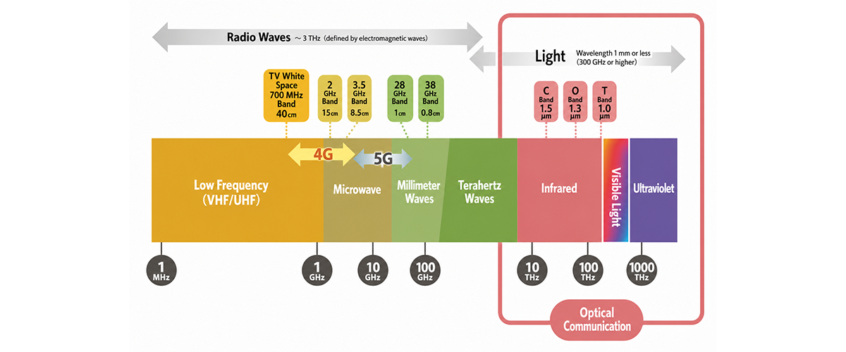
Figure 3. Wavelengths Used in Radio Communication and Optical Wireless Communication
3. Cn² and Scintillation
As mentioned earlier, optical wireless communication links that pass through a ground station always experience some signal loss due to atmospheric absorption and scattering. For satellite links under clear skies and at a sufficiently high elevation angle, this loss may be only a few decibels, depending on the wavelength.
Weather conditions, however, can have a much greater impact. Fog and clouds can dramatically weaken an optical signal. Dense fog can introduce attenuation of up to 300 dB per kilometer, while even thin clouds in the troposphere can cause losses of around 50 dB per kilometer. Under these conditions, the communication link may be completely unavailable.
Another important challenge is the fluctuation of the received optical signal caused by atmospheric turbulence. In radio communication, a similar phenomenon is known as fading. In optical wireless communication, it is called scintillation.
Scintillation occurs because the atmosphere is constantly in motion. Turbulent air flows mix regions of different temperatures, creating random changes in the refractive index of the air. As light travels through these turbulent regions, its wavefront becomes distorted. This causes constructive and destructive interference, making the received signal fluctuate over time. The twinkling of stars or distant city lights on a warm evening is a familiar example of this phenomenon.
The strength of scintillation is closely related to Cn² (the refractive index structure parameter), a widely used measure of atmospheric turbulence. A larger Cn² indicates stronger turbulence and, therefore, stronger scintillation. For this reason, estimating Cn² is an important step when calculating a link budget, as it helps predict the signal loss caused by atmospheric turbulence.
Because Cn² represents the strength of atmospheric turbulence, its value naturally changes with altitude. It is highest near the ground, decreases with increasing altitude, and approaches nearly zero at around 20 km. As a result, the impact of turbulence depends strongly on the type of communication link.
In an uplink from the ground to a satellite, the optical beam encounters the strongest turbulence immediately after it is transmitted. By the time it reaches the satellite, the beam has already been distorted into an irregular pattern, producing strong scintillation (Figure 4).
A downlink, on the other hand, travels through the vacuum of space for most of its path. The light encounters atmospheric turbulence only during the final portion of its journey, below an altitude of about 20 km. As a result, scintillation is generally less severe, especially when the ground station is located in an area with favorable atmospheric conditions.
A horizontal terrestrial link, such as one used for last-mile connectivity, experiences a different situation. In this case, Cn² can be treated as nearly constant along the propagation path. However, because the light travels entirely through the turbulent air near the Earth's surface, scintillation can become significant even over distances of only a few kilometers.
Fortunately, optical wireless communication offers several techniques for reducing the effects of atmospheric turbulence. As shown in Table 2, these methods can be broadly divided into two categories: those that stabilize the optical signal itself, and those that improve the reliability of the digital data after it has been received.
One of the most widely used techniques for stabilizing the optical signal is fine tracking. A fine-tracking system continuously adjusts the pointing direction of the transmitter or receiver to keep the optical beam accurately aligned. This not only helps reduce the effects of scintillation but also compensates for mechanical vibration and pointing errors. As a result, fine tracking has become a standard feature in many experimental optical communication systems.
Another well-established technique is adaptive optics, which was originally developed for astronomy. Adaptive optics uses a deformable mirror to correct distortions in the incoming wavefront, allowing the light to be coupled into an optical fiber more efficiently.
Increasing the aperture size is another effective approach. In radio communication, larger antennas are mainly used to increase antenna gain. In optical wireless communication, a larger telescope provides the additional benefit of averaging out atmospheric turbulence. Because different parts of a large aperture receive light that has traveled through slightly different regions of the atmosphere, fluctuations tend to cancel each other out, reducing the overall intensity variation.
Compensation can also be applied after the optical signal has been received, at the level of the digital data. The most common technique is error correction coding, which is a standard feature of virtually every modern communication system, including optical wireless communication.
For short periods of signal fading, forward error correction (FEC) combined with an interleaver can effectively recover burst errors. An interleaver temporarily stores the incoming bit stream and rearranges the data before transmission so that consecutive errors caused by fading are spread out. This makes it much easier for the error correction code to recover the original data.
However, these techniques also have practical limitations. They can only compensate for signal fluctuations up to a certain speed, and implementing very large interleavers—often requiring tens of megabytes of high-speed memory—becomes increasingly difficult. Large interleavers also introduce additional communication delay. As a result, improving only the physical layer is generally not enough to achieve the desired level of system availability.
This is why countermeasures at higher communication layers are also important. Like other communication systems, optical wireless links can use retransmission protocols when data is lost. One widely used approach is Automatic Repeat reQuest (ARQ), which requests that missing or corrupted packets be retransmitted. ARQ was adopted in the 200 Gbps ground-to-LEO optical communication demonstration conducted by NASA and MIT Lincoln Laboratory. [Reference 2]
To maintain a highly available optical communication service even when fog or clouds block individual links, a single ground station is often not sufficient. Instead, operators deploy site diversity, where multiple ground stations are distributed across different locations. By placing stations far enough apart that they are unlikely to experience the same weather at the same time, the probability that at least one station has clear skies is greatly increased.
A commonly used rule of thumb is that weather conditions, especially cloud cover, become much less correlated over distances of about 80 km or more. Ground station networks are therefore designed to take advantage of this effect and maximize overall link availability.
As these examples show, achieving the target availability of an optical wireless communication system requires a cross-layer approach. Techniques ranging from beam stabilization and adaptive optics at the physical layer to error correction, retransmission protocols, and network-level site diversity all work together to mitigate the effects of atmospheric turbulence and weather.
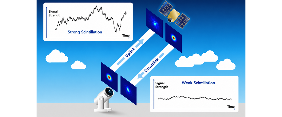
Figure 4. Asymmetric Scintillation in Ground-to-Space Optical Links
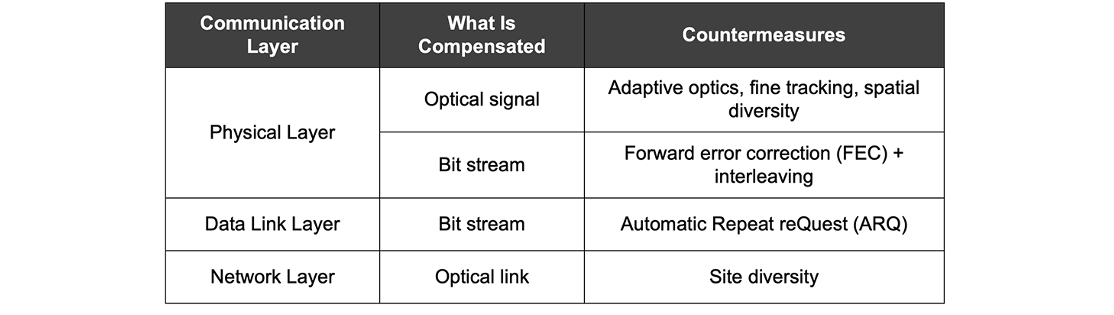
Table 2. Countermeasures at Different Communication Layers
4. The Future of NTN with a HAPS Layer
To summarize what we have discussed so far, the biggest challenges for optical communication between space and the ground are clouds, fog, and atmospheric turbulence in the lower atmosphere. These effects can interrupt communication or significantly degrade signal quality, which is why site diversity using multiple ground stations is so important.
Now imagine a future where High-Altitude Platform Stations (HAPS) form their own constellation and are connected by an optical wireless network. In that case, the role of site diversity changes dramatically.
With conventional ground stations, site diversity is mainly a matter of infrastructure: how many ground stations can be built and where they are located. Because clouds are usually localized, spreading ground stations over a wide area increases the chance that at least one will have clear skies. However, optical ground stations are expensive to build and operate, so increasing their number also increases deployment and maintenance costs.
In contrast, if the HAPS layer itself is connected by optical links in a mesh network, site diversity becomes a networking problem rather than an infrastructure problem. Instead of relying on a fixed set of ground stations, the network can simply choose the HAPS located above a region with clear weather to act as the gateway (GW) at that moment. In other words, whichever HAPS has the best connection to the ground can dynamically become the gateway.
This architecture offers much greater flexibility than an NTN built using only Low Earth Orbit (LEO) satellites. Even if LEO satellites are interconnected through optical inter-satellite links (ISLs), communication with the ground still depends on fixed gateway locations. In addition, LEO satellites move rapidly across the sky, making it more difficult to align communication with a satellite that happens to be above clear weather. This places tighter constraints on the number and placement of gateway stations, as well as on scheduling and network operation.
There is another challenge as well. Because LEO satellites move at high orbital speeds, ground stations must continuously point ahead of the satellite's position to maintain the optical link. This large pointing adjustment makes it more difficult to compensate for beam wander caused by atmospheric turbulence, often requiring a wider optical beam. As a result, both the design and operation of gateway stations become more complex.
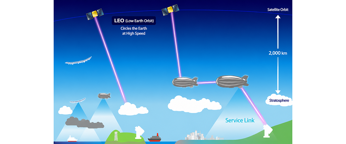
Figure 5. An NTN Architecture with a HAPS Layer
With a HAPS constellation in place, however, satellites in LEO or GEO no longer communicate directly with a fixed point on the ground. Instead, they communicate with a layer of platforms in the sky. The primary optical link between the satellite and HAPS remains above the clouds, avoiding the lower atmosphere and eliminating problems associated with low elevation angles. In effect, the most challenging part of the atmosphere is removed from the primary communication path.
If the HAPS layer is interconnected by optical links, traffic can also be routed within the HAPS network before being sent to the ground. This allows the network to dynamically select the gateway location based on current weather conditions, sending traffic to the region with the clearest skies. In this architecture, site diversity is achieved not by building more ground stations, but by giving the network greater flexibility in routing traffic.
For the final link between HAPS and the ground, it becomes practical to use radio frequencies, such as the Ka band, alongside optical communication. The key advantage here is the much shorter communication distance. At an altitude of around 20 km, a HAPS platform only needs to support links of roughly 100 km or less to reach a ground station. Compared with a direct satellite-to-ground optical link, this greatly relaxes the requirements for antenna gain, pointing accuracy, and transmit power.
This creates a natural division of roles: optical communication carries high-capacity traffic through space and across the HAPS network, while short-range RF communication provides a reliable connection from HAPS to the ground, even under less favorable weather conditions.
Introducing an optical HAPS layer could therefore transform NTN from a collection of dedicated point-to-point links into something much closer to a space-based Internet. Although this vision is still under active study, SoftBank is actively pursuing both optical communication technologies for future NTN systems and optical communication networks based on the HAPS layer.
Reference
[1] A. Carrasco-Casado, H. Takenaka, D. Kolev, Y. Munemasa, H. Kunimori, K. Suzuki, T. Fuse, T. Kubooka, M. Akioka, Y. Koyama and M. Toyoshima, "LEO-to-ground optical communications using SOTA (Small Optical TrAnsponder) – Payload verification results and experiments on space quantum communications," Acta Astronautica, vol. 139, pp. 377-384, 2017.
[2] Kathleen Riesing, Curt Schieler, Bryan Bilyeu, Jesse Chang, Ajay Garg, Noah Gilbert, Andrew Horvath, Robert Reeve, Bryan Robinson and Jade Wang, “Operations and Results from the 200 Gbps TBIRD Laser Communication Mission”, 37th Annual Small Satellite Conference, Aug. 2023.