Contents
- Blog
- Wireless, Network, Computing
SoftBank Demonstrates Higher 5G Uplink Throughput with a Transformer Neural Receiver
#AI-RAN #AIforRAN #Transformer
Nov 02, 2026
SoftBank Corp.

Over-the-air tests with a commercial smartphone show up to 60.5% higher uplink L1 throughput with NVIDIA Aerial.
SoftBank integrated a Transformer-based neural receiver into NVIDIA Aerial's 5G Layer 1 (L1) and tested it over the air (OTA) with a commercial smartphone using a single uplink spatial layer in a shield room. We captured uplink IQ, fine-tuned the model, and compared the two receiver paths with link adaptation enabled.
At the setting plotted near −0.6 dB on the calibrated signal-to-interference-plus-noise ratio (SINR) scale, the neural receiver achieved a mean uplink L1 throughput of 47.9 Mbit/s, compared with 29.9 Mbit/s for the conventional receiver: a 60.5% gain. Its mean throughput was higher at all 15 settings tested with interference.
1. From channel interpolation to neural reception
SoftBank's earlier shield-room trial used a convolutional neural network (CNN) for uplink channel interpolation and increased throughput by approximately 20% over a non-AI baseline. A subsequent Transformer-based design achieved approximately 30% over the non-AI baseline, or about 8% over the CNN.
Channel interpolation estimates the radio channel between known reference signals. Our earlier models replaced this single stage. The neural receiver (NRx) is a learned front end that covers channel estimation, interpolation, equalization, and soft demapping, converting received IQ and reference information into soft bit estimates. Descrambling, rate recovery and LDPC decoding remain shared downstream stages. Figure 1 compares the processing scopes.
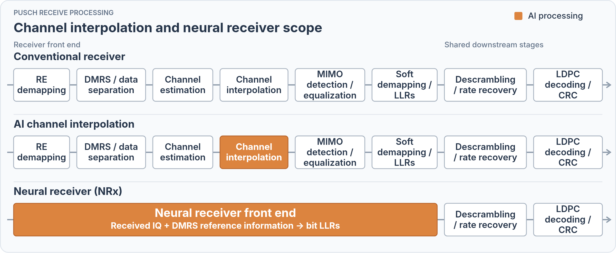
Figure 1. Processing scope of AI channel interpolation and the neural receiver
2. Turning IQ into soft bits
Our neural receiver takes received IQ and the corresponding demodulation reference signal (DMRS) information. It produces log-likelihood ratios (LLRs), which express confidence in each transmitted bit.
A CNN first combines nearby resource elements (REs). Self-attention can directly combine REs across the physical resource block (PRB), as illustrated in Figure 2.
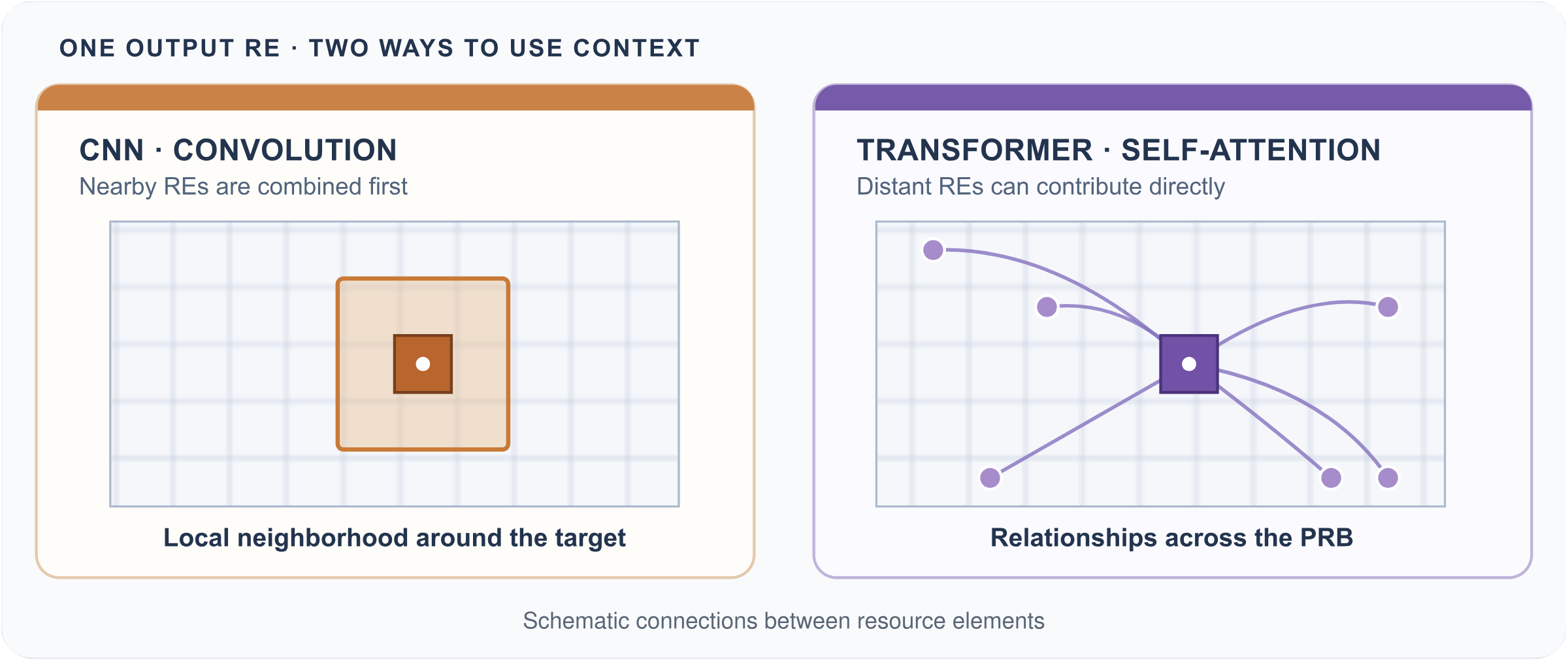
Figure 2. Local convolution and self-attention over a resource grid
The model follows SoftBank's published Transformer architecture. It treats each RE as a time-frequency token, projects its features into a shared representation, and adds time and frequency position information. Self-attention and feed-forward layers with residual connections combine these features. A small multilayer perceptron (MLP) and output projection produce the LLRs. The published architecture omits Layer Normalization in its early stages to retain signal magnitude for physical-layer estimation, and uses Layer Normalization later in the network. The cuPHY input adapter passes the received I/Q components to the model without additional RMS normalization or a gain multiplier.
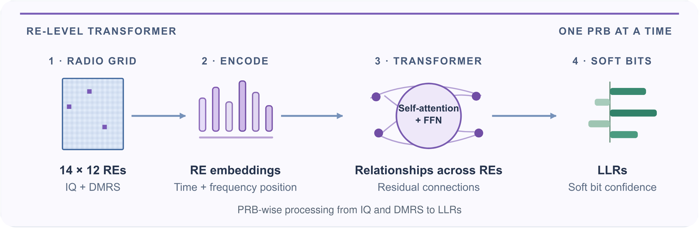
Figure 3. Transformer processing from IQ and DMRS to soft-bit LLRs
The evaluated configuration uses one Transformer encoder layer and a projection width of 64. Attention operates within each PRB, across its 14 OFDM symbols and 12 subcarriers. The output interface provides up to eight LLRs per RE, with the required bit positions selected for the scheduled modulation. The recorded OTA MCS modes correspond to QPSK, 16QAM and 64QAM.
3. Integrating the receiver into Aerial L1
The OTA testbed runs OpenAirInterface (OAI) L2/L3 and NVIDIA Aerial CUDA-Accelerated RAN L1, including the GPU-accelerated cuPHY receiver, on an NVIDIA GH200 Grace Hopper Superchip. We integrated the neural receiver into the physical uplink shared channel (PUSCH) receive path. The evaluation used Aerial/cuBB 26-1-cubb, a customized OAI gNB image, and a TensorRT 10.14.1 FP16 engine.
Receiver configuration selects the conventional or neural front end before each run. The neural adapter supports one uplink spatial layer. PUSCH transmissions outside the neural path's supported conditions use the conventional receiver. Both paths feed the same descrambling, de-rate matching, low-density parity-check (LDPC) decoding, and cyclic redundancy check (CRC) stages. OAI handles MAC scheduling and retransmissions.
The baseline configuration recorded for the testbed uses multistage MMSE channel estimation with delay estimation and MMSE-IRC equalization with RBLW covariance shrinkage.
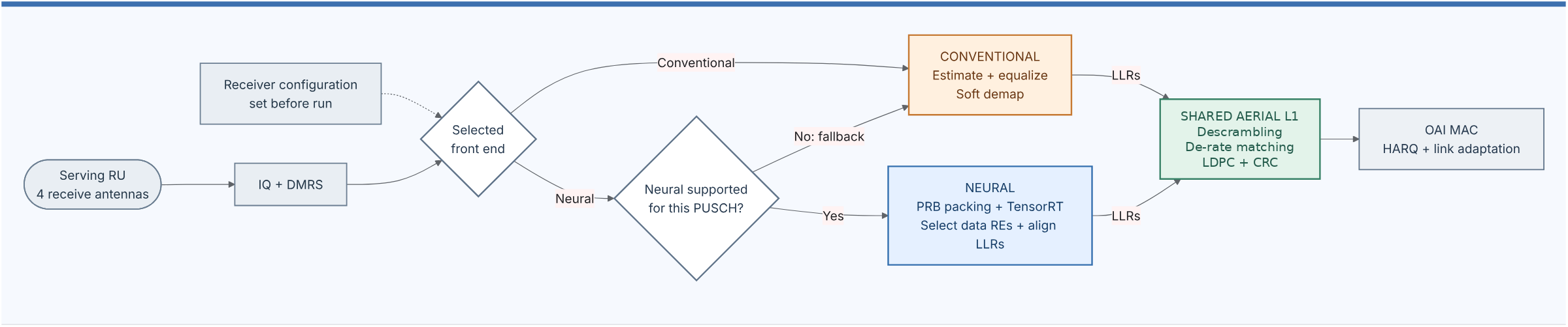
Figure 4. Conventional and neural front ends feeding the shared NVIDIA Aerial L1 decoder
Before decoding, we remove reference-signal positions from the model output and align the remaining data-bit LLRs to the order expected by Aerial. The adapter's default output scaling multiplies the LLRs by four, with explicit LLR clipping disabled by default.
4. Training on captured radio signals
The model design drew on wireless simulations using NVIDIA Sionna. The evaluated weight lineage began with random initialization and training on captured IQ, followed by successive fine-tuning stages. For this OTA trial, we fine-tuned it on IQ captured from the handset. Aerial Data Lake, running in the live Aerial L1 controller, recorded FAPI uplink scheduling information and fronthaul IQ.
The final fine-tuning stage used 13,200 slots from six capture segments, with 64QAM transmissions and single-symbol Type 1 DMRS using port 0, one CDM group without data and no additional DMRS positions. Each segment was split chronologically into 90% training and 10% validation, giving 11,880 training slots and 1,320 validation slots in total. All PRBs from a slot stayed in the same split.
We matched the FAPI and IQ records by timestamp, frame, and slot. Using pyAerial and cuPHY, we reconstructed reference signals and conventional-receiver LLRs, then checked the decoding path with LDPC and CRC. Reconstructed transmitted coded bits supplied most training targets; when unavailable, we used the signs of conventional-receiver LLRs. Fine-tuning used binary cross-entropy loss.
We fine-tuned the model in TensorFlow on the development GPU, exported it through ONNX, and built a TensorRT FP16 engine. That engine was deployed back into the live Aerial L1 and kept fixed throughout the subsequent live OTA evaluation. Training captures and OTA evaluation shared the handset and installation, while the evaluation covered a wider sweep of uplink power-control settings.
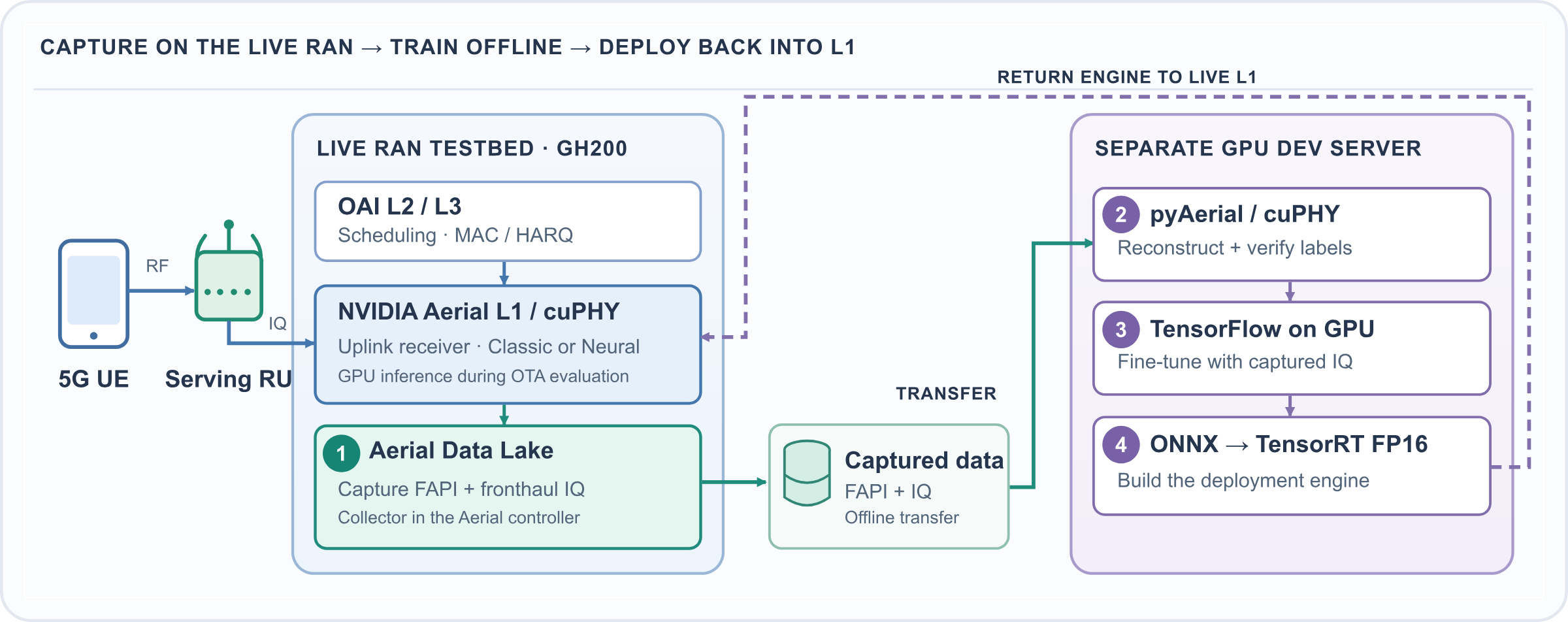
Figure 5. IQ capture, offline training, and deployment to Aerial L1
5. OTA evaluation under interference
The evaluation used a commercial 5G smartphone and a serving radio unit (RU) in a shield room, with a separate gNB/RU transmitting NR PDSCH on the same 100 MHz channel. The cell operated in n78 with a 100 MHz carrier, 30 kHz subcarrier spacing, four receive antennas, and one uplink spatial layer. The median reported PRB allocation was 273 in each measurement window, based on 12 OAI UE-statistics samples taken five seconds apart.
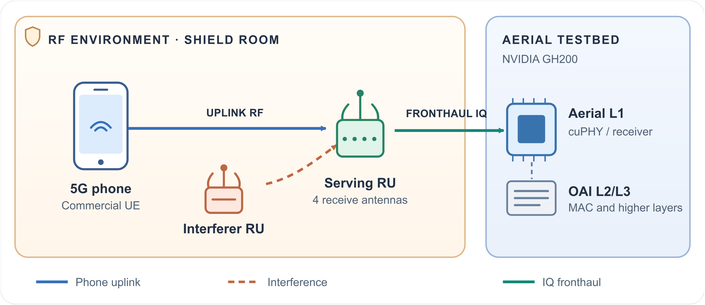
Figure 6. Shield-room OTA setup with interference. Illustration: SoftBank
With the interferer held at a fixed setting, we swept 15 uplink power-control settings in 1 dB steps. Each receiver path was measured in three roughly one-minute windows per setting, giving 90 windows across the two paths. At each measurement setting, we held transmit-power-control (TPC) commands fixed at a 0 dB adjustment to keep power-control conditions consistent between receiver runs, while link adaptation continued to select the modulation and coding scheme (MCS).
Both receiver paths used the same OAI build and scheduler settings, with four UDP streams configured for a combined offered uplink load of 120 Mbit/s. The two paths were measured in separate live OTA runs, with repeats associated by control setting and run label. RU RSSI and sampled UE statistics recorded receive levels, MCS, PRB allocation and link status.
Figure 7 uses a SINR scale calibrated from the conventional receiver's estimates. We retained the 1 dB spacing of the power-control settings and fitted a single offset to the conventional receiver's mean reported SINR estimates at the nine highest settings. The same mapping was applied to both receiver paths. Each throughput value is the mean of three measurement-window medians.
Uplink L1 throughput is the payload-bit rate of transport blocks that pass CRC, including MAC headers and padding. A failed transmission contributes no bits; a retransmission contributes its payload when decoding succeeds.
Each window median is calculated from per-second L1 throughput reports, and the three windows are equally weighted. The shaded bands show the observed minimum and maximum of the three window medians.
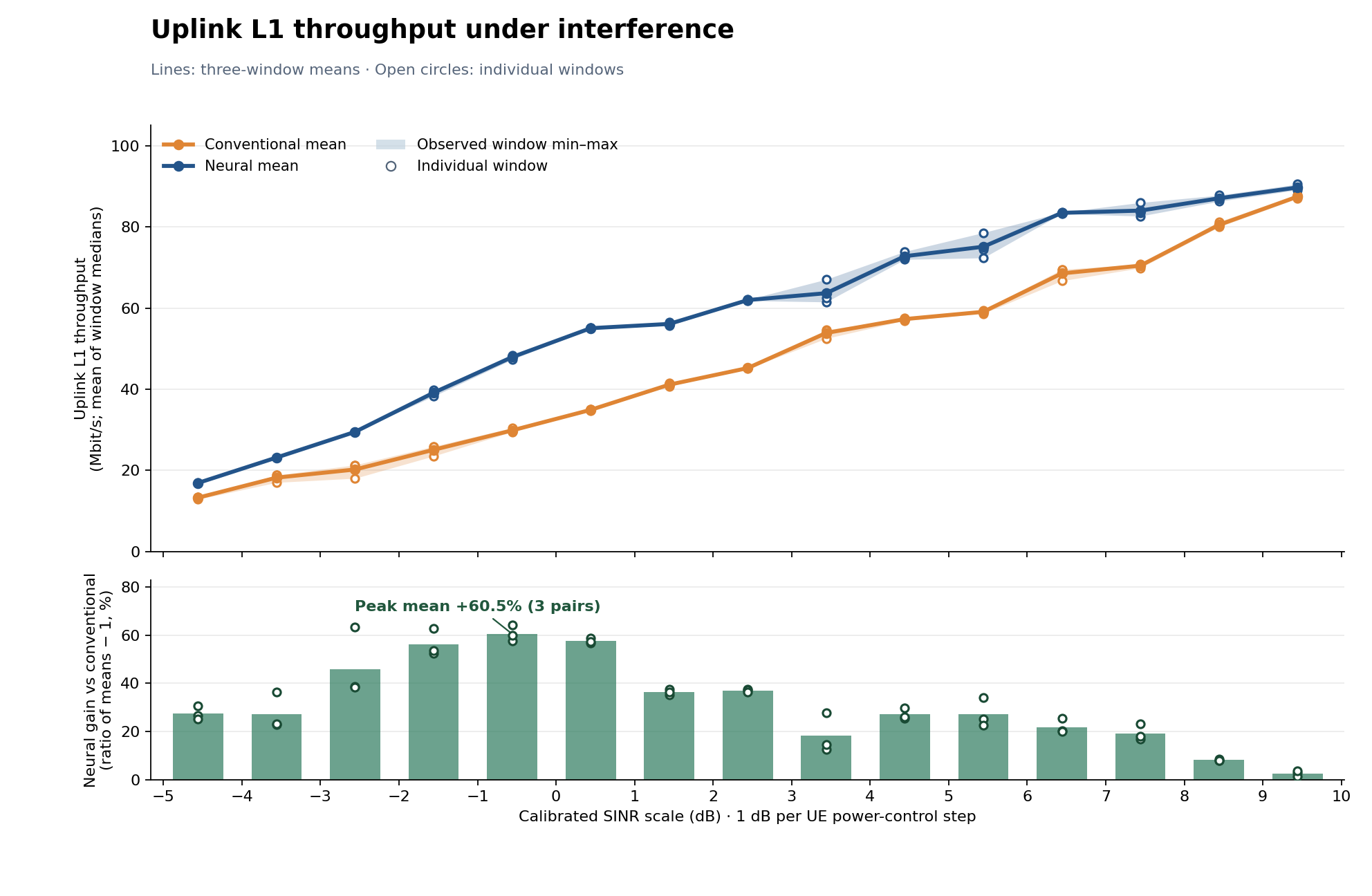
Figure 7. Uplink L1 throughput and neural-receiver gain under interference
All settings from the 15-point sweep, with link adaptation enabled.
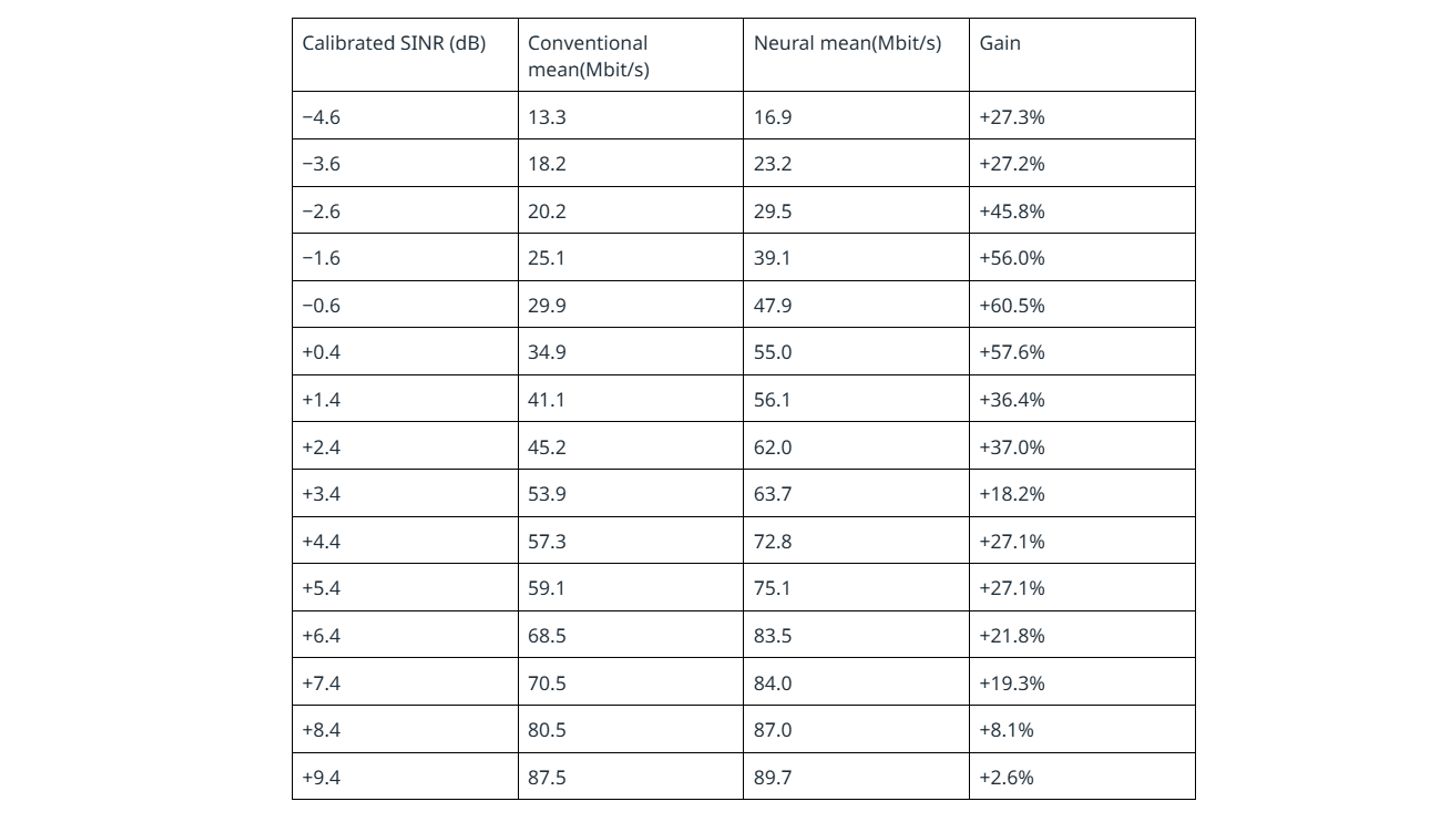
Gains use the unrounded three-window means; throughput values are displayed to one decimal place.
At the setting plotted near −0.6 dB, uplink reports showed mainly MCS 4–5 on the conventional path and MCS 8 on the neural path. First-transmission failure rates estimated from the OAI HARQ round counters were similar: 9.6% and 9.0%, respectively. The throughput improvement was accompanied by a higher MCS under link adaptation.
6. Conclusion
The neural receiver's mean uplink L1 throughput exceeded the conventional receiver's at all 15 settings with interference in this single-layer, shield-room trial. The largest gain was 60.5%, at the setting plotted near −0.6 dB on the calibrated SINR scale.
This trial extended our Transformer-based processing from channel interpolation to channel estimation, equalization, and soft demapping in an operating 5G receiver. Captured handset IQ supported fine- tuning, and the resulting TensorRT engine ran in Aerial L1 with the existing decoder and OAI scheduling and retransmission controls. The next phase of the trial will evaluate two-layer uplink operation and test generalization across a broader range of channel and interference conditions.
References and Related Links
SoftBank's CNN-based uplink channel-interpolation trial (2025)
SoftBank's Transformer-based channel-interpolation trial (2025)
Kawai and Koodli, A Unified Transformer Architecture for Low-Latency and Scalable Wireless Signal Processing
Author