Contents
Blogs
- Jun 15, 2023
- Blog
- Wireless
Exploring New Possibilities of High-Speed Communication Technology Through Art.
#FSOC/Terahertz, #Event
Scroll
![]()
EXPERIMENT 2:Teleffectence
![]()

Artwork Introduction Video
System Configuration
In this artwork, we utilize the ultra-low latency and high-capacity free-space optical communication (FSOC) to connect two locations: Museum of the Light and Nagasaka Community Station. This enables the real-time transmission of two-way 8K high-definition video and audio. The equipment configuration at both venues is as follows: cameras installed at Museum of the Light capture the monitors, which are then transmitted via FSOC and displayed on the monitors at Nagasaka Community Station. Similarly, cameras installed at Nagasaka Community Station capture the monitors, which are then displayed on the monitors at the Museum of Light. By repeating these processes with ultra-low latency, a mirrored effect is created. The same applies to the audio, where sound generated at Museum of the Light is recorded with a microphone and played through the speakers at Nagasaka Community Station. The sound is then recorded with a microphone at the same venue and played back through the speakers at Museum of the Light. By repeating this process with ultra-low latency, a state is created where the sound resonates between the two spaces. These elements come together in a work that is made possible by the ultra-low latency FSOC, creating the illusion of two spaces merging into one.
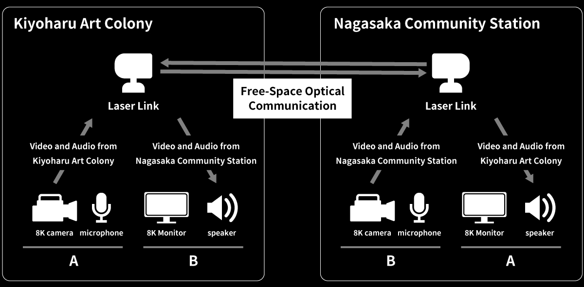
Equipment Configuration Diagram

System Configuration Diagram
Free-Space Optical Communication (FSOC)
FSOC is a wireless communication technology that utilizes light. It operates in a higher frequency band than radio waves, enabling ultra-low latency and high-capacity communication. This demonstration of real-time 8K video transmission using outdoor FSOC represents the world-first achievement.

Main Parameters
*Latency is measured by RTT (Round Trip Time)
Light is scattered and absorbed by moisture in the atmosphere, causing the beam to weaken. Therefore, in conditions of high humidity such as rainy weather, communication can become unstable, presenting significant operational challenges. To address this issue, SoftBank utilized a proprietary simulator to predict the communication availability based on the amount of moisture in the atmosphere and implemented preventive measures in advance. After conducting one month of verification prior to the exhibition, we achieved a successful prediction of communication availability with an error margin of 0.3%.
More detailed technical explanation and information about our efforts regarding FSOC can be found on the following page.
https://www.softbank.jp/en/corp/technology/research/story-event/012/
8K Video and Audio Transmission Equipment
We used the following equipment, in collaboration with ASTRODESIGN,Inc., to build the real-time transmission system for 8K video and audio.

Main equipments used for the artwork
Clock Synchronization
In order to transmit captured video using cameras and display it correctly on the receiving end, it is necessary to synchronize the clocks between the transmitting and receiving devices. In typical displays, the video is displayed by sequentially refreshing several hundred to several thousand horizontal lines from top to bottom.
During video transmission, the exchange of video data occurs at the line level or frame level (where a frame represents an image composed of a specified number of lines). The transmitting device sends the video based on its clock's cycle and video timing, while the receiving device plays back the video based on its clock's cycle and video timing. However, if the clock's cycle and video timing differ, there may be missing or duplicated line information during line-level transmission, as shown in the diagram below (in this case, line-level transmission is used for low-latency real-time transmission). To prevent such video distortions, clock synchronization is required between the transmitting and receiving devices.
While BNC cables or HDMI cables can transmit clock and video timing information simultaneously, it is not possible to transmit clock information simultaneously using internet protocols. Therefore, an additional method for clock synchronization is needed.

The reason for clock synchronization requirement
We used the PTP (Precision Time Protocol) to achieve clock synchronization in this artwork. PTP is a protocol defined in IEEE 1588-2019, which allows for highly accurate clock synchronization at the microsecond level. We install grandmasters at both the transmitting and receiving sites, synchronizing the clocks of devices within their respective networks. The grandmasters serve as a reference based on GPS (GNSS), enabling high precision and stable time synchronization.
However, there are certain constraints related to the equipment and installation. When transmitting PTP over the network, the network switches along the transmission path need to support PTP, which is often not the case. The presence of PTP-unsupported network switches poses a limitation. Additionally, as mentioned earlier, GPS (GNSS) is commonly used to align the reference time of the grandmasters between sites. However, the installation of GPS antennas is constrained by factors such as location and human resources.
Therefore, in this case, we achieve clock synchronization by transmitting PTP via FSOC. A Grand Master is installed at one location, and its internal clock is transmitted to the remote location via FSOC using a separate channel from the video transmission. Both locations share and synchronize their clocks, ensuring time synchronization. FSOC enables communication with a delay on the order of microseconds, allowing us to eliminate additional equipment such as GPS antennas and significantly reduce constraints.

Configuration of Clock Synchronization Using FSOC
Reducing End-to-End Latency
To achieve low-latency video transmission, it is necessary to consider the entire end-to-end process, from video encoding/decoding to display rendering on the monitor. The diagram below illustrates the breakdown of latency in this artwork. In particular, for leveraging the ultra-low latency of FSOC, it is crucial to reduce latency in areas other than the network segments that are usually not of concern. JPEG-XS* is adopted for video encoding/decoding, which achieves lower latency compression without high compression ratios, resulting in a total delay of 1ms. Even in the output to the monitor, which is typically not noticeable in daily life, there is actually a delay of tens to hundreds of milliseconds. By applying settings that simplify the monitor's rendering process, we have achieved a delay of less than 30 milliseconds. Further latency reduction is possible by utilizing low-latency monitors designed for professional use, among other options.

Breakdown of Delays in this Artwork
*JPEG-XS is an image compression standard developed by the JPEG working group and standardized in 2019. Its key feature is prioritizing image quality over compression ratio. As mentioned earlier, it enables visually lossless image compression with a compression ratio of approximately 1/6 (1/2 to 1/15). Additionally, the lightweight compression algorithm contributes to its low-latency characteristic. In JPEG-XS, there is no need for inter-frame processing (compression/decompression using information from consecutive frames). Compression/decompression processes are completed on a per-line basis, and there is no need to wait for accumulation of data for a full frame or for subsequent lines, allowing for low-latency processing. These characteristics make JPEG-XS suitable for applications such as streaming video transmission.

Overview of JPEG XS processing
To further reduce latency in the monitor output, we conducted a simple verification using a low-latency monitor. The video below shows the simultaneous output of footage captured by a single camera to both a regular monitor and a low-latency monitor. The camera used is the same model as the artwork, and for the regular monitor, it is connected using an SDI cable, an SDI-HDMI converter, and an HDMI cable, similar to the artwork setup. The low-latency monitor, being compatible with the SDI standard, is directly connected to the camera using an SDI cable.As evident from the video, the latter demonstrates lower latency in displaying the footage compared to the former. This is because the low-latency monitor has higher rendering performance and does not involve the processing of SDI-HDMI conversion.
![]()

Latency comparison of a general monitor and a low latency monitor
Daito Manabe Exhibition "EXPERIMENT" Special Website
We are currently hosting a special website where you can find an overview of the exhibited artworks and a behind-the-scenes video showcasing the production process. Please visit the website below to explore more.
